Eureka AIR delivers breakthrough ideas for toughest innovation challenges, trusted by R&D personnel around the world.

A Premixed Preevaporation Combustion Chamber Using a Radial Film-forming Main Combustion Stage

A technology of main combustion stage and combustion chamber, which is applied in the direction of combustion chamber, continuous combustion chamber, combustion method, etc., can solve the problems of inability to meet the low pollution requirements of the engine, high CO and UHC emissions, uneven local equivalence ratio, etc., to achieve The effect of low pollution emission, complete combustion and simple structure

Active Publication Date: 2014-10-15
BEIHANG UNIV
View PDF5 Cites 0 Cited by
  • Summary
  • Abstract
  • Description
  • Claims
  • Application Information

AI Technical Summary

Problems solved by technology

In small working conditions, the equivalence ratio of the combustion zone is very low, which is far below the equivalence ratio range required for low-pollution combustion. At this time, although NOx emissions are low, CO and UHC emissions are high
In addition, because the conventional combustion chamber generally adopts the diffusion combustion method, the local equivalence ratio is not uniform, so for the conventional combustion chamber, it cannot meet the low pollution requirements in the entire engine operating range

Method used

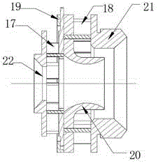
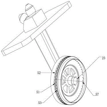

Image

  • A Premixed Preevaporation Combustion Chamber Using a Radial Film-forming Main Combustion Stage
  • A Premixed Preevaporation Combustion Chamber Using a Radial Film-forming Main Combustion Stage
  • A Premixed Preevaporation Combustion Chamber Using a Radial Film-forming Main Combustion Stage

Examples


Embodiment Construction

[0035] figure 1 It is a schematic diagram of the engine structure, including a low-pressure compressor 1, a high-pressure compressor 2, a combustion chamber 3, a high-pressure turbine 4 and a low-pressure turbine 5. When the engine is working, the air is compressed by the low-pressure compressor 1 and enters the high-pressure compressor 2. The high-pressure air then enters the combustion chamber 3 to burn with fuel. The high-temperature and high-pressure gas formed after combustion enters the high-pressure turbine 4 and low-pressure turbine 5, and passes through the turbine. Do work to drive the high-pressure compressor 2 and the low-pressure compressor 1 respectively;

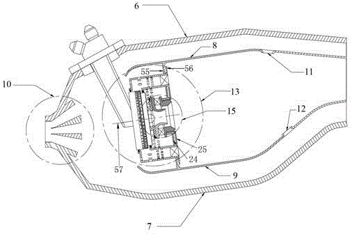
[0036] Such as figure 2 As shown, the combustion chamber 3 adopts a single-annular cavity structure, and the casing 6 outside the combustion chamber and the casing 7 inside the combustion chamber constitute the outer contour of the combustion chamber, and are connected with the high-pressure compressor 2 and...


PUM


Abstract

A premixing and pre-evaporation combustor for a main combustion stage using radial film formation consists of a diffuser, an outer combustor case, an inner combustor case, a pre-combustion stage, the main-combustion stage, a flame barrel outer wall and a flame barrel inner wall, wherein the flame of the pre-combustion stage is stabilized by a low-speed return flow zone formed by cyclone generated when a pre-combustion stage cyclone assembly enters the combustor; after being sprayed out by a plurality of tangential spraying openings of a main combustion stage nozzle, fuel oil of the main combustion stage spreads in a fuel oil film formation region and realizes connection, so that a peripheral continuous oil film is formed; the cyclone of an upstream cyclone ring of the main combustion stage nozzle and the cyclone of a downstream cyclone ring of the main combustion stage nozzle secondarily atomize the fuel oil, the fuel oil is brought to a premixing and pre-evaporation section to evaporate and is mixed with air, and uniform oil-gas mixtures are formed at an outlet of the premixing and pre-evaporation section, are jetted into a flame barrel, are ignited by the flame of the pre-combustion stage and then are combusted. The premixing and pre-evaporation combustor is simple in structure; and pollutant discharge can be effectively reduced while a normal working state of an aerial engine is guaranteed.

Description

technical field [0001] The invention relates to a low-pollution combustion chamber of an aviation gas turbine using premixed combustion technology, which adopts a staged combustion mode. Fuel is fed into the membrane. The invention can ensure a wide stable working range of the combustion chamber while reducing the pollution discharge of the combustion chamber. Background technique [0002] The basic performance and structural distribution of modern aero-engine combustors have reached a fairly high level, but there are still a lot of problems and challenges for modern aero-engine combustors. The development and application of new materials, new processes, new structures, and new concepts It is the source to ensure its continuous progress. [0003] The main development trend of modern civil aeroengine combustors is low-pollution combustion. Combustion chambers of civil aeroengines must meet increasingly stringent aeroengine pollution emission standards. The currently adopt...

Claims


Application Information

Patent Timeline
Patent Type & Authority Patents(China)
IPC IPC(8): F23R3/52F23R3/58F23R3/30F23R3/38
Inventor 傅奇慧张弛林宇震付镇柏
Owner BEIHANG UNIV
Why Eureka
Eureka Blog
Learn More