Multicore connector for connecting a plurality of contact pads of a circuit board to a plurality of contacts in a one-to-one correspondence

a multi-core connector and contact pad technology, applied in the direction of coupling contact members, coupling device connections, coupling protective earth/shielding arrangements, etc., can solve the problems of affecting the transmission of high-speed signals, and completely grounded, so as to improve the emi characteristic of multi-core connectors and flexible design

Inactive Publication Date: 2005-05-24
ITT CANNON
View PDF8 Cites 24 Cited by
  • Summary
  • Abstract
  • Description
  • Claims
  • Application Information

AI Technical Summary

Benefits of technology

[0021]The contacts 34 on the receptacle 2 side can be modularized in units of a specific number of contacts as shown in FIG. 6. Although the present invention is not limited to the modularization of contacts, use of a structure with a plurality of contact modules enables a great many contact sections to be formed. Use of a plurality of contact modules conforming to the same standard according to the number of contacts needed makes it possible to form various types of multicore connectors easily according to the number of cores needed. Consequently, it is possible to give flexibility to the design.
[0022]Furthermore, a plurality of spring contacts bringing the shell section of the plug frame 3 and the receptacle housing 11 into contact with each other, or grounding plate springs 25 can be provided on the inner periphery of the receptacle housing 11. This structure makes a reliable electrical connection between the plug frame 3 and the grounded receptacle housing 11, which provides a structure capable of improving the EMI characteristic of the multicore connector related to the present invention.

Problems solved by technology

In addition, the signals they have to transmit and receive have become more diversified and complex.
However, in the conventional multicore connector of FIG. 11, the contacts 108 and 109 are long, which permits crosstalk or a similar problem to occur between the contacts, depending on usage.
Furthermore, since spring actions are needed, this lengthens the signal line, making interference, such as crosstalk, liable to take place in the transmission characteristic of the electric signals, which tends to have an adverse effect on the transmission of high-speed signals.
As a result, the connector 200 is made larger on the whole and the parts mounting area is made smaller, which is a problem.
In addition, there is another problem: even if the plug housing 203 and receptacle housing 209 are made of a metal, it is difficult to make electrical connection to cause them to be grounded completely.

Method used


Image

  • Multicore connector for connecting a plurality of contact pads of a circuit board to a plurality of contacts in a one-to-one correspondence
  • Multicore connector for connecting a plurality of contact pads of a circuit board to a plurality of contacts in a one-to-one correspondence
  • Multicore connector for connecting a plurality of contact pads of a circuit board to a plurality of contacts in a one-to-one correspondence

Examples


Embodiment Construction

[0038]Referring to the accompanying drawings, embodiments of the present invention will be explained. FIGS. 1 to 10 show multicore connectors according to embodiments of the present invention. In the detailed explanation below and the description of the drawings, like elements are indicated by like reference numerals.

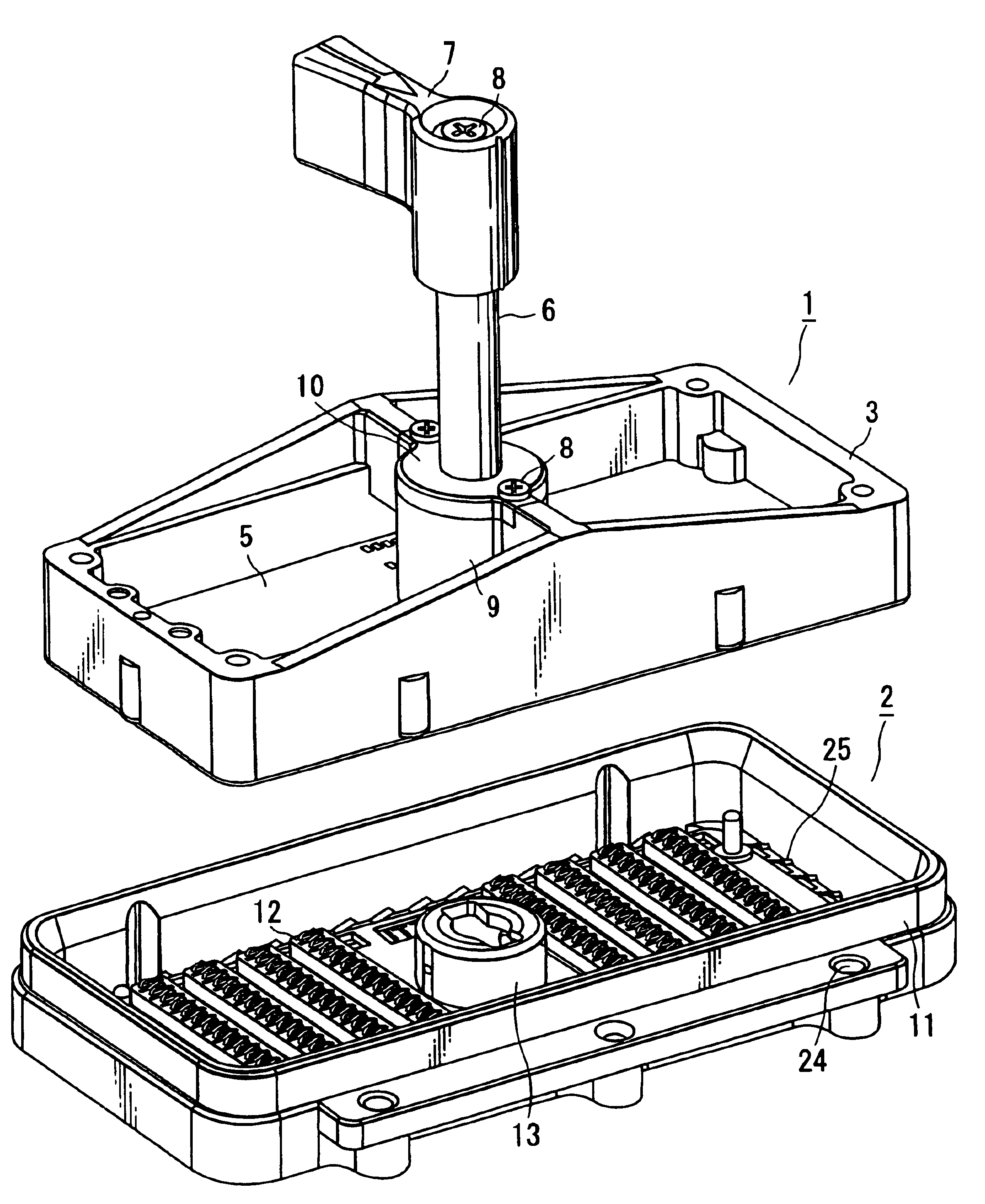
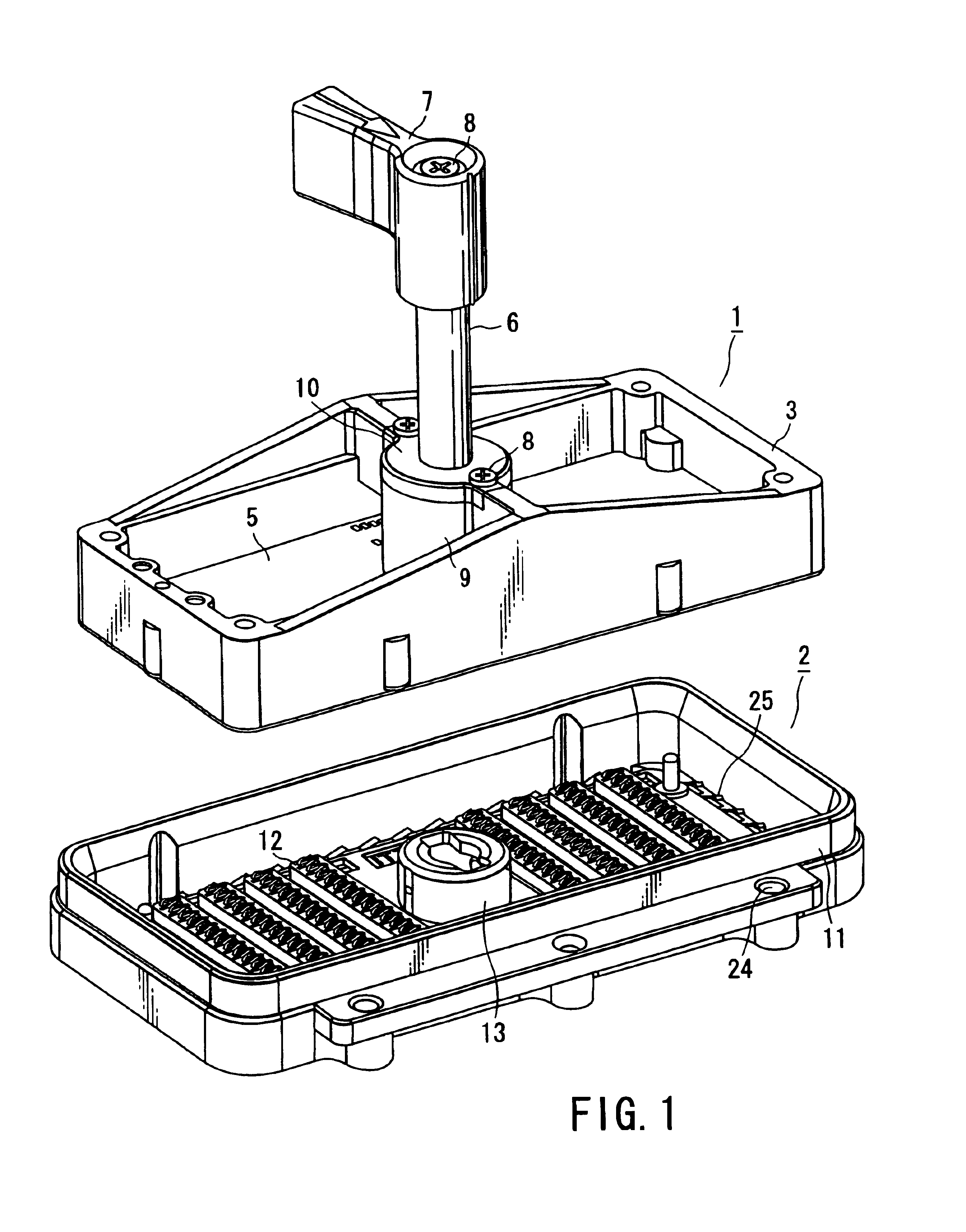
[0039]FIG. 1 is a perspective view, from diagonally above, of a plug 1 and a receptacle 2 constituting a multicore connector according to the present invention. The terms representing directions, including up, down, longitudinal, and lateral directions, used in this specification are used on the basis of examples shown in the accompanying drawings. Actually, the multicore connectors may be placed diagonally or upside down on the accompanying drawings.

[0040]In FIG. 1, a plug 1 includes a plug frame 3 made of, for example, a metal member, so that at least its surface is conductive, a plug board 5 attached to the lower part of the plug frame 3 with, for example, screws 4 (...


PUM


Abstract

A connector has a board with a plurality of contact pads electrically connected to a plurality of signal lines on one side. The connector also has a modularized structural unit on the other side. The structural unit includes a plurality of spring contacts as the mate to which the contact pads are electrically connected. The connector further has a shaft provided near the central part of the board and perpendicular to the board and a roller provided on the structural unit. To combine the contact pads and the contacts, the shaft is rotated to cause the rollers to engage with a projecting part provided at the tip of the shaft. The roller is provided higher in position than the circuit board on which the connector is to be mounted.

Description

CROSS-REFERENCE TO RELATED APPLICATIONS[0001]This application is based upon and claims the benefit of priority from the prior Japanese Patent Application No. 2002-188407, filed Jun. 27, 2002, the entire contents of which are incorporated herein by reference.BACKGROUND OF THE INVENTION[0002]1. Field of the Invention[0003]This invention relates to a connector usable in, for example, medical instruments, such as ultrasonic diagnostic equipment, semiconductor testing equipment, computers, and industrial equipment with a multicore electric input / output section, such as communications equipment.[0004]2. Description of the Related Art[0005]More particularly, this invention relates to a multicore connector with a plug and a receptacle used for an electrical connection between electronic apparatuses utilizing a multi-core cable or the like.[0006]Sophisticated electronic apparatuses, including medical instruments, semiconductor testing equipment, computers, and communications equipment, have ...

Claims


Application Information

Patent Timeline
Patent Type & Authority Patents(United States)
IPC IPC(8): H01R12/00H01R12/16H01R9/03H01R13/621H01R13/639
CPCH01R12/714H01R12/88Y10S439/953
Inventor YAMADA, MASAHIROIKENAKA, KAZUO
Owner ITT CANNON
Why Eureka
Try Eureka