Surgical saw blade comprising recesses in the working area

a saw blade and working area technology, applied in the field of surgical saw blades, can solve the problems of difficult or even impossible optical monitoring of sawing operation, inability to provide the necessary strength and stability, and unstable construction, etc., and achieves the effects of low cost, high stability and strength, and simple structur

Inactive Publication Date: 2005-05-24
GEBR BRASSELER
View PDF14 Cites 40 Cited by
  • Summary
  • Abstract
  • Description
  • Claims
  • Application Information

AI Technical Summary

Benefits of technology

[0003]It is the object of the present invention to provide a surgical saw blade of the above-mentioned type which, while being of a simple str

Problems solved by technology

As a result of the planar design of the saw blades, these conceal the working area during specific operations, so that it is difficult or even impossible to monitor the sawing operati

Method used


Image

  • Surgical saw blade comprising recesses in the working area
  • Surgical saw blade comprising recesses in the working area
  • Surgical saw blade comprising recesses in the working area

Examples


Embodiment Construction

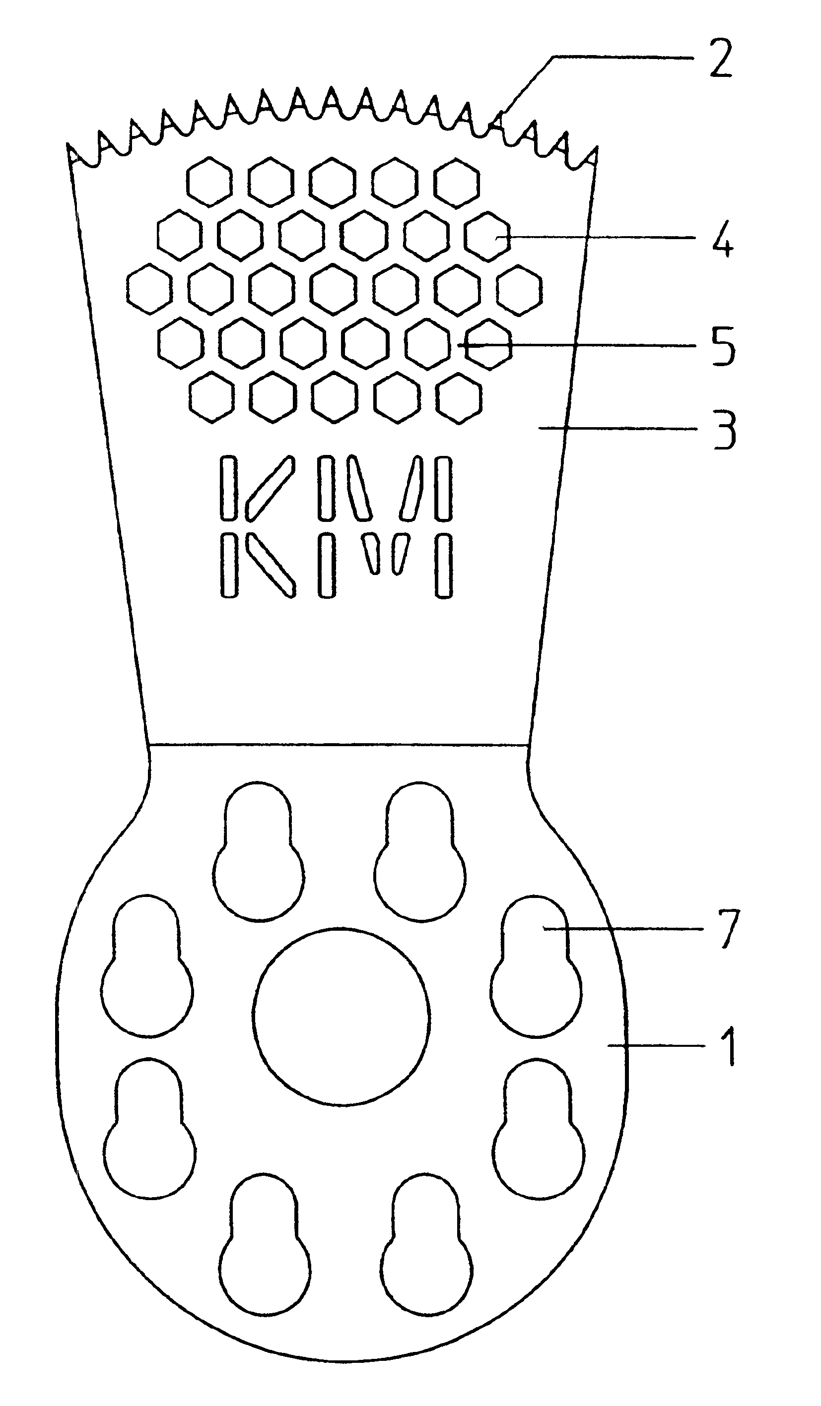
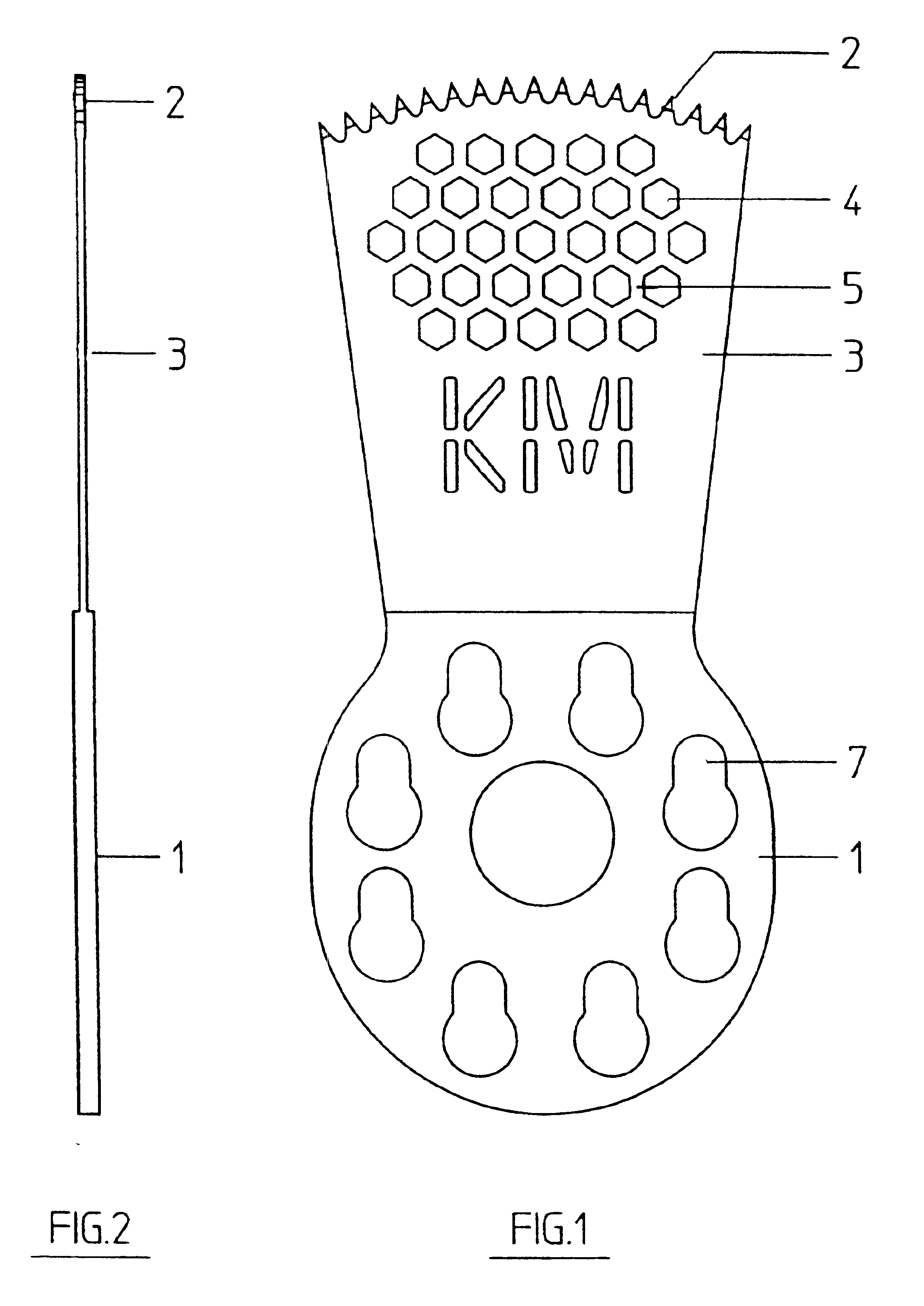
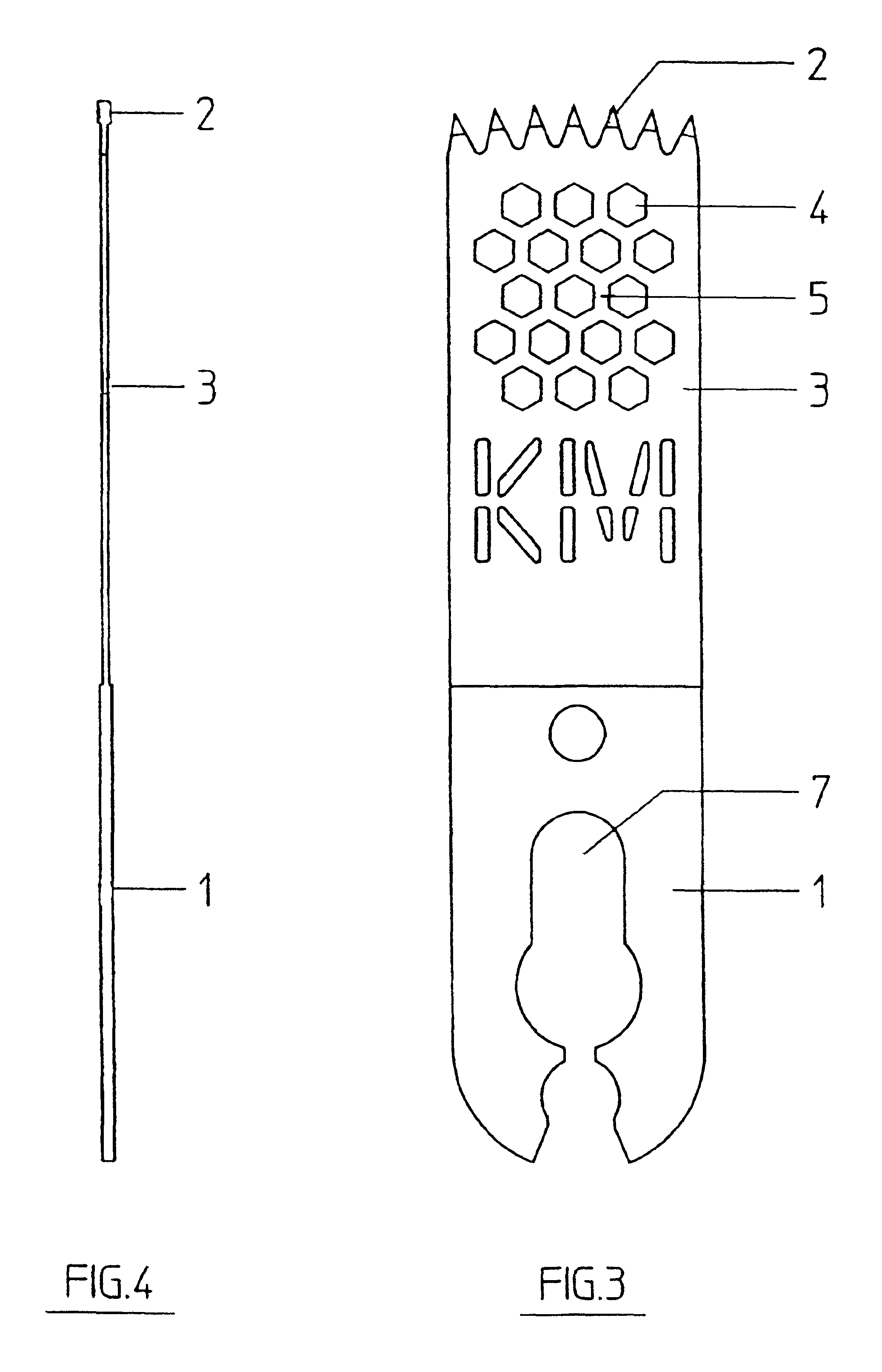
[0018]As can be seen in FIG. 1, the saw blade comprises a substantially circular clamping portion 1 which is provided with a plurality of mounting openings 7. Both the mounting openings and the dimension of the clamping portion 1 are known from the prior art, so that a detailed description is omitted. In one embodiment, the diameter of the clamping portion 1 is approximately 16 mm.

[0019]The clamping portion is followed by a working area 3 whose front arcuate edge is provided with a toothing 2, the center point of the arc preferably being positioned in the center of rotation or pivotal point of the saw blade. In one embodiment, toothing 2 may have a width of approximately 15 mm and the total length of the saw blade may be approximately 35 mm.

[0020]A plurality of hexagonal recesses that are arranged in honeycomb-like fashion are formed in the working area 3, the recesses 4 being separated from one another by webs 5. The honeycomb structure shows a high degree of strength, so that the ...


PUM


Abstract

The present invention relates to a surgical saw blade comprising a clamping portion and a working area provided with a toothing, wherein a plurality of recesses are formed in the working area.

Description

BACKGROUND OF THE INVENTION[0001]The present invention relates to a surgical saw blade comprising a clamping portion and a working area provided with a toothing. Surgical saw blades of the described type are known from the prior art in many different designs. They are mounted on a drive unit by which they can be induced to perform an oscillating reciprocating movement. It is thereby possible to carry out, for instance, precise bone cuts. The saw blades can be guided manually, but it is also possible to use the blades together with templates to produce precise predetermined cuts.[0002]As a result of the planar design of the saw blades, these conceal the working area during specific operations, so that it is difficult or even impossible to monitor the sawing operation optically. That is why it has already been suggested that the working area should be provided with a large recess so that the toothing is only connected via lateral edge portions to the clamping portion. Such constructio...

Claims


Application Information

Patent Timeline
IPC IPC(8): A61B17/14
CPCA61B17/14A61B17/148A61B17/141A61B17/142
Inventor DANGER, KARL-HEINZKULLMER, MICHAEL
Owner GEBR BRASSELER
Why Eureka
Try Eureka