Electric membrane switch with seven contact positions

Inactive Publication Date: 2005-05-24
LEAR CORP
View PDF9 Cites 29 Cited by
  • Summary
  • Abstract
  • Description
  • Claims
  • Application Information

AI Technical Summary

Benefits of technology

[0008]Another object of the invention is providing for said switch said electric contact means located in the cones fixed solidly to the membrane, and which have a c

Problems solved by technology

Many other embodiment examples could be mentioned in which multiple switch devices such as those mentioned are used, but in the majority of the ca

Method used


Image

  • Electric membrane switch with seven contact positions
  • Electric membrane switch with seven contact positions

Examples


Example

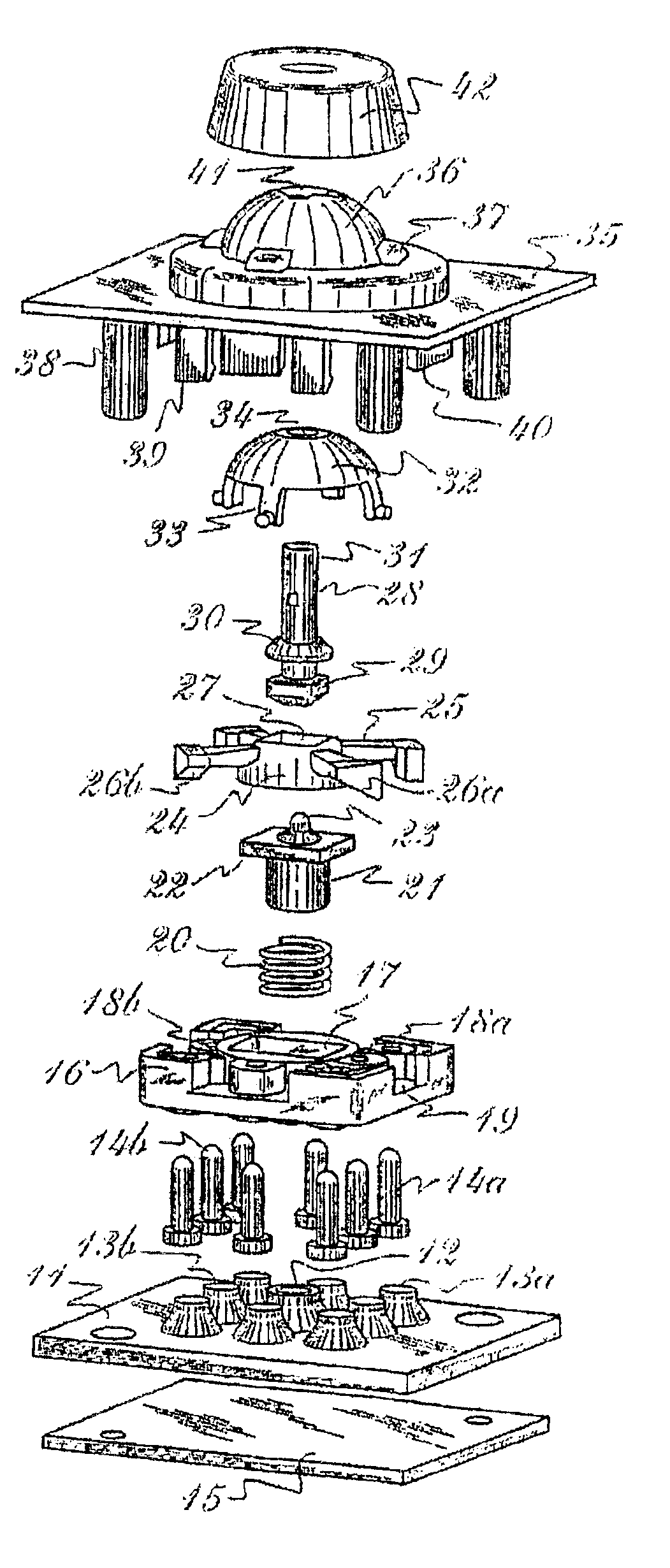
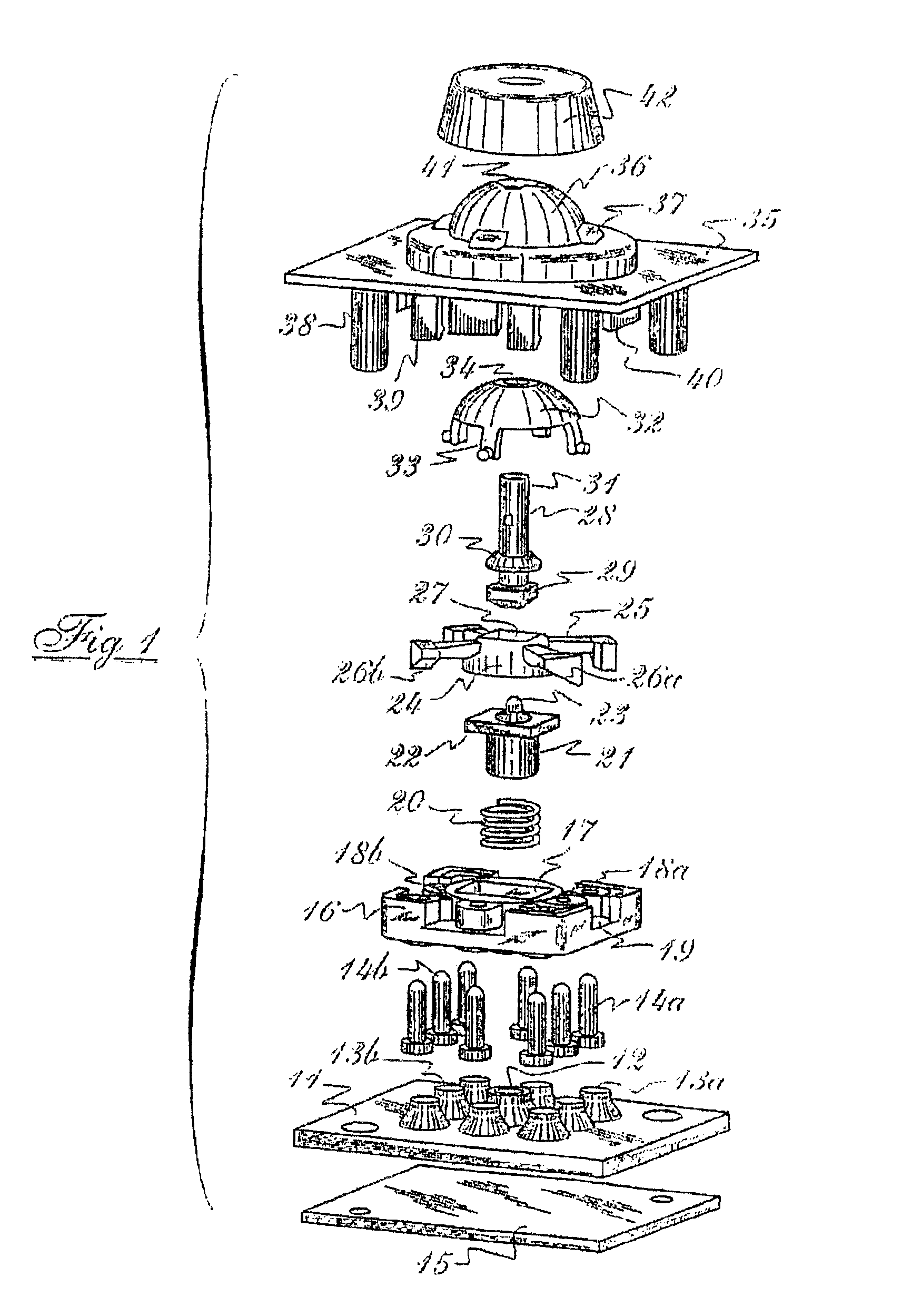
[0012]The qualities and advantages of the invention will become evident for all those skilled persons in the art throughout the development of the following detailed description, which is carried out in relation to the attached figure, and which shows a currently preferred embodiment, from among other possible embodiments, of the switch concerning us, constituted from the descriptions of the present embodiment, which are provided with a purely illustrative and in no case limiting character.

[0013]With regard to the drawing, 11 designates a rectangular-shaped laminar membrane which has a central cone 12 on its upper surface solidly fixed to it, four cones 13a arranged in a diagonal position, each one in the direction of the corresponding corner of the membrane 11, and four other intermediate cones 13b in line with each two of the previous cones 13a; and all of them having a contact wafer inside, not shown in the drawing, suitable for selectively establishing contact with the circuits ...


PUM


Abstract

An electric switch of mechanical structure and functioning, and with electric contacts by means of membranes, suitable for optionally arranging seven different control signals by means of other such contact positions selectively induced by a single button means, four of these positions are differentiated when a slight rolling movement is carried out on said button means in any of four opposite directions and 90° equidistant from each other, a fifth contact position in its clockwise axial rotation, the sixth position by means of its counter-clockwise rotation, and a last contact position by means of a linear pulsating movement.

Description

BACKGROUND OF INVENTION[0001]An electric switch of mechanical structure and functioning and of electric contacts by means of membranes, suitable for optionally establishing different control signals by means of other such contact positions selectively induced on a single button means, four of these being differentiated positions when carrying out a slight rolling motion on said button means in any of four opposite directions and 90° equidistant from each other, a fifth contact position in its clockwise axial rotation, the sixth one by means of its counter-clockwise rotation, and a last contact position by means of a linear pulsating movement.DESCRIPTION OF THE STATE OF THE ART[0002]The use of different compact, electric or electromechanical switch devices is widely known, capable of establishing on demand different signals with which to control different operations in distant, independent mechanisms or apparatuses.[0003]For example, and from among a wide variety of them, electric co...

Claims


Application Information

Patent Timeline
IPC IPC(8): G05G9/00G05G9/02H01H25/04G05G9/047
CPCG05G9/02H01H25/041H01H2025/043G05G2009/04744
Inventor GAVALDA, EDUARD TORRENTS
Owner LEAR CORP
Why Eureka
Try Eureka