Non-linear junction detector

a detector and nonlinear junction technology, applied in the direction of geological measurements, electric/magnetic detection for well-logging, using reradiation, etc., can solve the problems of unwanted device triggering, higher illumination levels, and increase the risk of interference for casual observers, so as to reduce or avoid the increase of the illumination level of the target junction

Inactive Publication Date: 2005-05-24
AUDIOTEL INT
View PDF7 Cites 73 Cited by
  • Summary
  • Abstract
  • Description
  • Claims
  • Application Information

AI Technical Summary

Benefits of technology

[0035]Embodiments of the present invention may provide a method and apparatus for the detection of non-linear junctions that reduces, or avoids increase in, the illumination level of the target junction as the target is being approached.
[0036]Embodiments of the present invention may also eliminate, reduce or minimise undesirable effects in non-linear junction detection such as those mentioned in the background section above.

Problems solved by technology

4.b) System power (e.g. battery life) is wasted by allowing the level of the illuminating signal to increase beyond the point at which detection occurs.c) In certain applications e.g. improvised explosive device detection (IED) or explosive ordnance disposal (EOD), an increase in illuminating signal at the target junction can lead to unwanted device triggering.d) Interference to office equipment may occur which can alert others to the fact that an NLJD is in use.e) Higher illumination levels increase the risk of interference to a casual observer.

Method used


Image

  • Non-linear junction detector
  • Non-linear junction detector
  • Non-linear junction detector

Examples


case 1

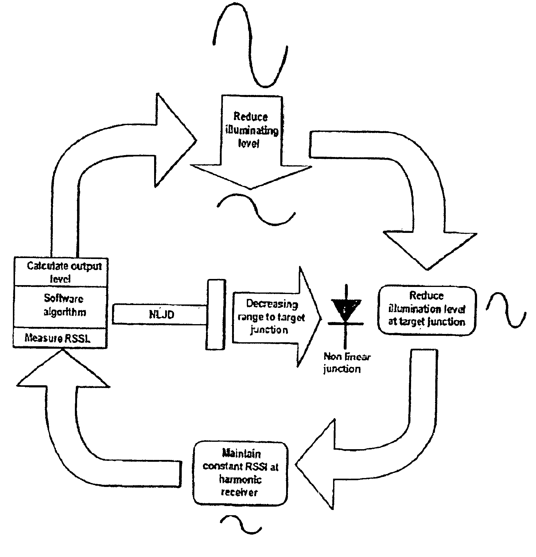
[0091] NLJD Approaching a Target Junction

[0092]With reference to FIG. 6, the following description of the algorithm operation relates to the NLJD moving toward a target non-linear junction

[0093]At step 601, the system reads the current 2nd harmonic RSSI value and in step 602 determines a difference value, NEWPDIF between the current RSSI value and the maximum (target) allowed RSSI value. When the RSSI from the 2nd harmonic receiver rises above the MAX_INPUT_RSSI level (ie. NEWPDIF>0, step 603) the software algorithm will decrease the illuminating signal level, via the TXPOTN variable discussed later, to drive the RSSI back to the MAX_INPUT_RSSI level.

[0094]The amount of decrease in the illuminating signal level, NEWPDIF, is determined by checking to see whether the value NEWPDIF exceeds a maximum allowed step size or not (step 604). If yes, the algorithm calculates NEWPDIF to be OLDPDIF+MAXSTEP (step 605) and if no, OLDPDIF+NEWPDIF (step 606).

[0095]The illuminating signal level can ...

case 2

[0101] NLJD Receding from a Target Junction

[0102]With further reference to FIG. 6, the following description of the algorithm operation relates to the NLJD moving away from a target non-linear junction.

[0103]When the RSSI from the 2nd harmonic receiver drops below the MAX_INPUT_RSSI level (ie. the test NEWPDIF>0 is not true, step 603), the software algorithm will increase the illuminating signal level, via the TXPOTN variable discussed later, to drive the RSSI back to the MAX_INPUT_RSSI level.

[0104]NEWPDIF is converted to a positive value (step 620) and the amount of increase in the illuminating signal level, NEWPDIF, is determined by checking to see whether the value NEWPDIF exceeds a maximum allowed step size or not (step 621). If yes, the algorithm calculates NEWPDIF to be OLDPDIF−MAXSTEP (step 622) and if no, OLDPDIF−NEWPDIF (step 623). If the recalculated NEWPDIF proves to be a negative number (step 624), the value is set to zero (step 625) and no change in power level occurs. ...


PUM


Abstract

A target junction is illuminated with energy at a fundamental RF frequency and reflections from the non-linear junction are analyzed to determine the type of junction detected. The power output level of a transmitter emitting the illuminating signal is automatically controlled so as to drive the signal strength of the received signals towards a predetermined value, e.g. a minimum threshold value. An indication of the current received signal strength, adjusted by a factor so as to compensate for any automatic adaptation in the actual transmitter power output level, may be provided to an operator.

Description

CROSS-REFERENCE TO RELATED APPLICATIONS[0001]This application is a 371 of PCT / GB02 / 00556 filed on Feb. 11, 2002, which claims priority from United Kingdom patent application number 0103429.7 filed on Feb. 13, 2001.FIELD OF THE INVENTION[0002]The present invention relates to methods and apparatus for detecting the presence of non-linear junctions.BACKGROUND OF THE INVENTION[0003]A non-linear junction detector (hereinafter “NLJD”) is a device which can be used to detect junctions between two materials exhibiting dissimilar electronic or electrical properties. Examples of non-linear junctions are semiconductor junctions or junctions between dissimilar metals. Such detectors are widely used in counter surveillance operations and in electronic ordnance detection.[0004]An exemplary operation of a prior art NLJD is illustrated in FIGS. 1 and 2.[0005]The NLJD 101 operates by illuminating a target junction 102 with energy 103 at a fundamental RF frequency. Reflections 104, 105 from the non-l...

Claims


Application Information

Patent Timeline
Patent Type & Authority Patents(United States)
IPC IPC(8): G01V3/12
CPCG01V3/12
Inventor HOLMES, STEVEN JOHNSTEPHEN, ANDREW BARRY
Owner AUDIOTEL INT
Why Eureka
Try Eureka