Eureka AIR delivers breakthrough ideas for toughest innovation challenges, trusted by R&D personnel around the world.

Spiral resonator-slot antenna

a spinning resonator and slot antenna technology, applied in the direction of slot antennas, antenna details, antennas, etc., can solve the problems of compromising the stealth of the ship, inconvenient operation, inconvenient maintenance,

Inactive Publication Date: 2005-05-24
THE JOHN HOPKINS UNIV SCHOOL OF MEDICINE
View PDF2 Cites 19 Cited by
  • Summary
  • Abstract
  • Description
  • Claims
  • Application Information

AI Technical Summary

Benefits of technology

The present invention provides a mobile resonator-slot antenna that meets the need for efficient wideband coverage regardless of the orientation of the slot. The antenna has a simple, space- and cost-efficient structure, and is low-profile and submarine-towed. The antenna includes a sliver of high dielectric material sandwiched between a single conductive sheet, which enhances its performance without detrimentally affecting its compactness. The location of the coaxial feeder's point of attachment is selected strictly as a function of the length of the sliver. The method of fabricating the antenna allows for a cost-efficient and simple process. Overall, the invention provides a solution for achieving efficient and wideband coverage in a compact and cost-effective way.

Problems solved by technology

Frequently, raising a mast may compromise the ship's stealth.
Furthermore, the original designs may be cumbersome, inefficient and cost prohibitive.
When the disclosed resonator-slot antenna was tested at sea, the results were not as good as those produced in the seawater tank.
Furthermore, the selection of dielectric materials and the dimensions of the tested antenna may also contribute to unsatisfactory gain characteristics produced by the tested antenna.
In particular, as discussed above, the problems confronting a resonator-slot antenna designer are the following: (1) cumbersome antenna topology and (2) antenna efficiency as a function of its orientation.

Method used


Image

  • Spiral resonator-slot antenna
  • Spiral resonator-slot antenna
  • Spiral resonator-slot antenna

Examples


Embodiment Construction

[0002]This invention was made with Government support under Contract No. N00024-98-D-8124 awarded by the Department of the Navy. The Government has certain rights in the invention.

BACKGROUND OF THE INVENTION

[0003]1. Field of the Invention

[0004]This invention relates generally to mobile wireless communication systems. More particularly, the present invention relates to mobile resonator-slot antennas.

[0005]2. Description of the Related Art

[0006]Air-to-ground and air-to-sea communication and radio transmission / reception use surface antennas for a variety of requirements such as, for example, military Ultra High Frequency (“UHF”) band (225-400 MHz), LOS, SATCOM, etc. For many years submarine UHF communication with satellites has been accomplished by using wide-band antennas incorporated within an extendable mast. Frequently, raising a mast may compromise the ship's stealth. Furthermore, the original designs may be cumbersome, inefficient and cost prohibitive. Numerous attempts directed ...


PUM


Abstract

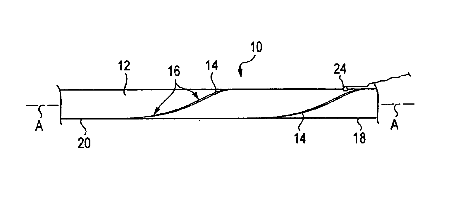
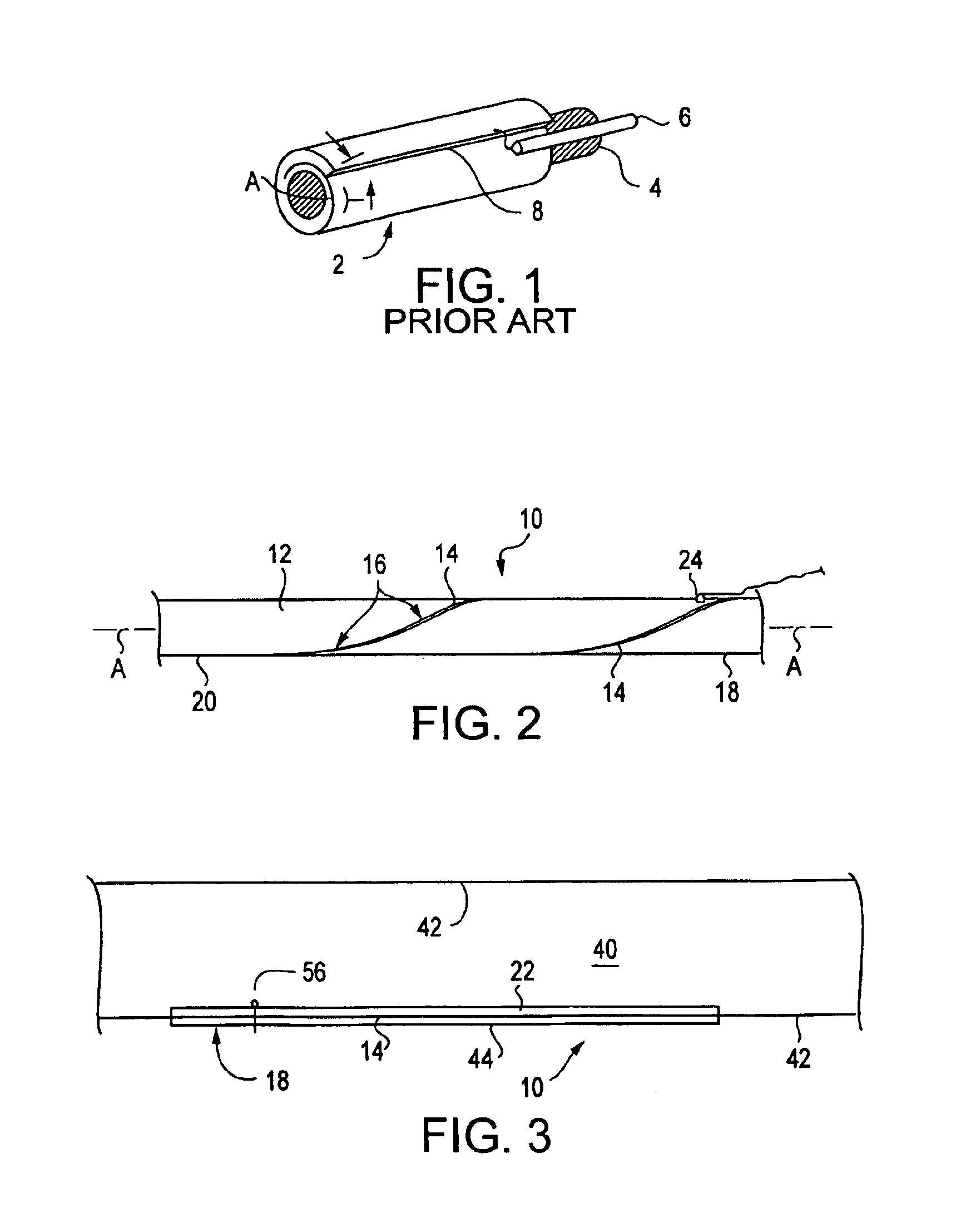
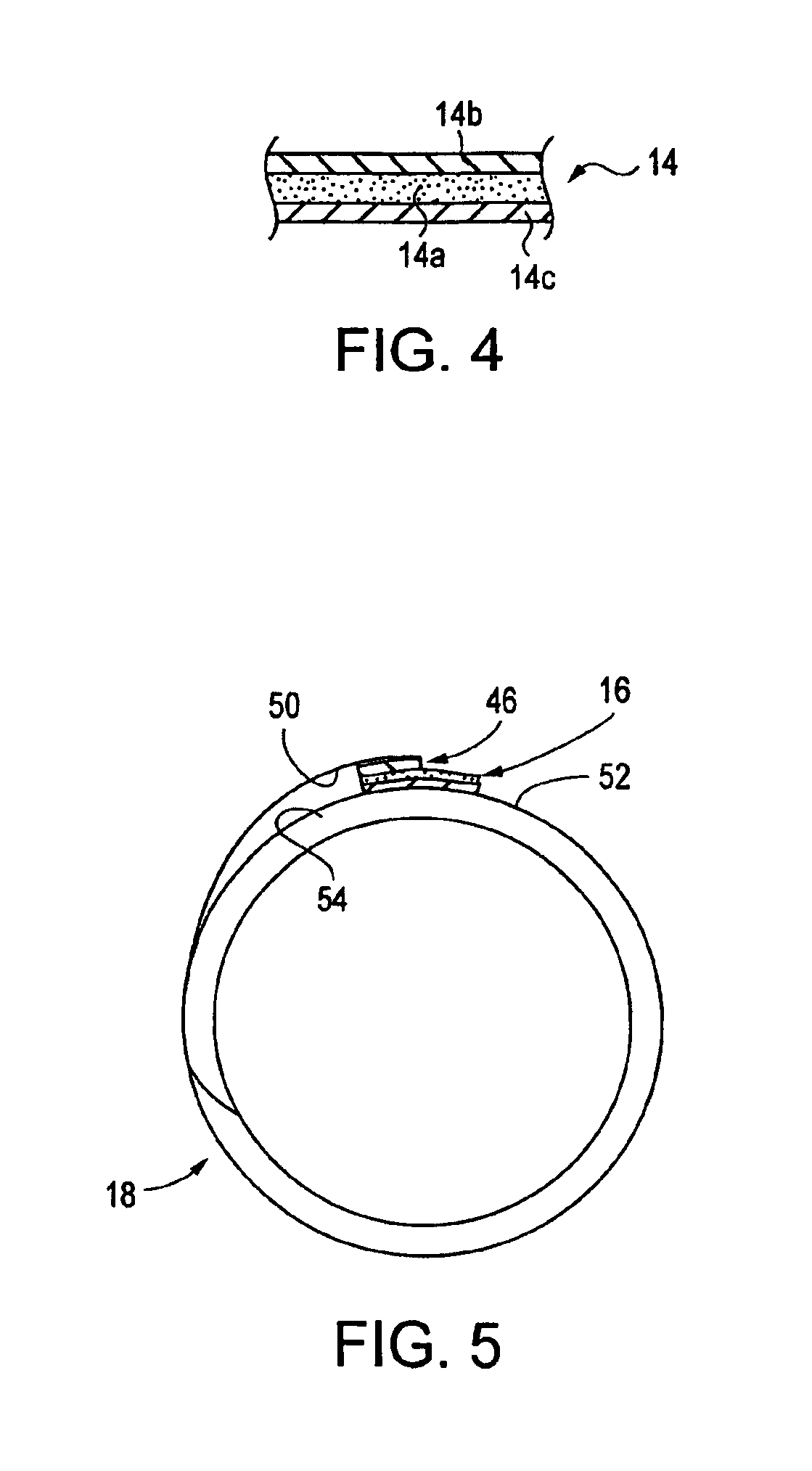
A resonator-slot antenna is configured to have a spiral of a conducive sheet material having at least one turn and extending along an axis with an elongated antenna slot helically wound around the axis in at least one full twist.

Description

CROSS-REFERENCE TO RELATED APPLICATION[0001]This application claims the benefit of U.S. Provisional Application No. 60 / 385,000 filed on Jun. 3, 2002, the contents of which are incorporated herein by reference.STATEMENT OF GOVERNMENTAL INTEREST[0002]This invention was made with Government support under Contract No. N00024-98-D-8124 awarded by the Department of the Navy. The Government has certain rights in the invention.BACKGROUND OF THE INVENTION[0003]1. Field of the Invention[0004]This invention relates generally to mobile wireless communication systems. More particularly, the present invention relates to mobile resonator-slot antennas.[0005]2. Description of the Related Art[0006]Air-to-ground and air-to-sea communication and radio transmission / reception use surface antennas for a variety of requirements such as, for example, military Ultra High Frequency (“UHF”) band (225-400 MHz), LOS, SATCOM, etc. For many years submarine UHF communication with satellites has been accomplished b...

Claims


Application Information

Patent Timeline
Patent Type & Authority Patents(United States)
IPC IPC(8): H01Q13/12H01Q13/10H01Q13/16
CPCH01Q13/10H01Q13/16H01Q13/12
Inventor SPARKS, KENNETH D.SORANNO, ROBERT T.
Owner THE JOHN HOPKINS UNIV SCHOOL OF MEDICINE
Why Eureka
Eureka Blog
Learn More