On-line device testing block integrated into a process control/safety system

Active Publication Date: 2005-05-24
FISHER-ROSEMOUNT SYST INC
View PDF10 Cites 34 Cited by
  • Summary
  • Abstract
  • Description
  • Claims
  • Application Information

AI Technical Summary

Benefits of technology

[0008]A process control or safety system within a process plant uses one or more testing blocks to effect the timely and safe operation of on-line self-testing routines within field devices, such as valves, used in the process control or safety system. These blocks, which are easy to implement and to place in the process control or safety system may enable the periodic or on-demand testing of field devices to be integrated into the normal and on-going operation of the process control or safety system without causing scheduling or connection problems and without the need to rely on maintenance or oth

Problems solved by technology

Furthermore, in many processes, a separate safety system is provided to detect significant safety related problems within the process plant and to automatically close valves, remove power from devices, switch flows within the plant, etc. when a problem occurs which might result in or lead to a serious hazard in the plant, such as a spill of toxic chemicals, an explosion, etc.
This fact is especially true with respect to valves and other field devices that have movable elements which have a tendency to become stuck and, therefore, not operate properly in response to control signals sent by a process control or safety system controller.
Unfortunately, both of these off-line testing techniques prevented operation of the process during the test, took a great deal of time and manpower, especially to remove and replace valves and other devices being tested, and did not enable the field devices to be tested on demand, e.g., whenever such a test is desired to be

Method used


Image

  • On-line device testing block integrated into a process control/safety system
  • On-line device testing block integrated into a process control/safety system
  • On-line device testing block integrated into a process control/safety system

Examples


Example

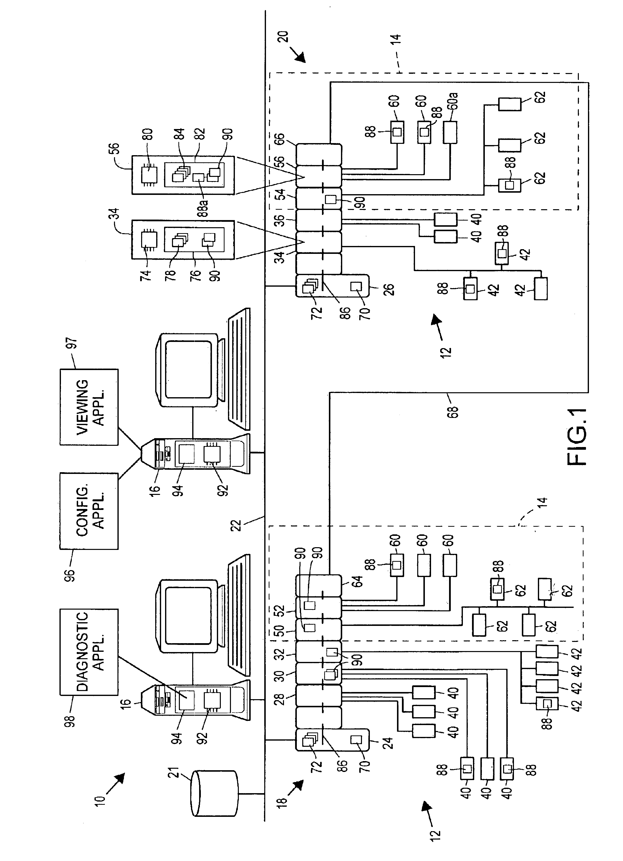
[0014]Referring now to FIG. 1, a process plant 10 includes a process control system 12 integrated with a safety system 14 (indicated by dotted lines), which generally operates as a Safety Instrumented System (SIS) to monitor and override the control provided by the process control system 12 to maximize the likely safe operation of the process plant 10. The process plant 10 (also referred to as the process control / safety system 10) also includes one or more host workstations, computers or user interfaces 16 (which may be any type of personal computers, workstations, PDAs, etc.) which are accessible by plant personnel, such as process control operators, maintenance personnel, safety engineers, etc. In the example illustrated in FIG. 1, two user interfaces 16 are shown as being connected to two separate process control / safety control nodes 18 and 20 and to a configuration database 21 via a common communication line or bus 22. The communication network 22 may be implemented using any de...


PUM


Abstract

A process control or safety system within a process plant uses one or more testing blocks to effect the timely and safe operation of on-line testing routines within field devices, such as valves, used in the process control or safety system. These testing blocks, which are easy to implement and to place in the process control or safety system, enable the periodic or on-demand testing of field devices to be integrated into the normal and on-going operation of the process control or safety system without causing scheduling or connection problems and without the need to rely on maintenance or other personnel, thereby providing better monitoring of the operational status of the field devices used within the process control and safety systems. This functionality is especially important in safety systems, in which it is desirable to timely monitor or assess the operational status of the devices used to shut the process down when an unsafe condition arises, so as to assure that initiation of a shut down by the safety system actually results in a shut down of the system.

Description

FIELD OF TECHNOLOGY[0001]The present invention relates generally to process control and safety systems used in process plants and, more particularly, to a testing entity used to control the operation of on-line device tests within a process plant.DESCRIPTION OF THE RELATED ART[0002]Process control systems, like those used in chemical, petroleum or other processes, typically include one or more process controllers communicatively coupled to at least one host or operator workstation and to one or more field devices via analog, digital or combined analog / digital buses or lines. The field devices, which may be, for example valves, valve positioners, switches and transmitters (e.g., temperature, pressure and flow rate sensors), perform functions within the process plant such as opening or closing valves and measuring process parameters. The process controllers receive signals indicative of process measurements made by the field devices and / or other information pertaining to the field dev...

Claims


Application Information

Patent Timeline
IPC IPC(8): G01M19/00G05B19/048G05B15/02G05B23/00G05B23/02G06F11/27G06F15/00G06F19/00H04L12/26G01M99/00G05B9/02
CPCG05B9/02G05B23/0256G05B2219/33331G05B2219/24054G05B23/00G05B23/02G06F11/27
Inventor OTT, MICHAEL G.LAW, GARYSTEVENSON, DENNISALI, RIYAZNIXON, MARKFORSYTHE, TIM
Owner FISHER-ROSEMOUNT SYST INC
Why Eureka
Try Eureka