
Maintaining a computer-generated design model

a computer-generated design and model technology, applied in the field of maintaining a computer-generated design model, can solve the problems of loss of parametric references and other linkages between assembly components, destroying design intent previously expressed by the designer, and manual restoration of design inten

Inactive Publication Date: 2005-05-24
DASSAULT SYST SOLIDWORKS CORP
View PDF7 Cites 76 Cited by
  • Summary
  • Abstract
  • Description
  • Claims
  • Application Information

AI Technical Summary

Benefits of technology

[0013]Implementations may include one or more of the following advantages. Integrity of the relationships between components of a modeled object can be automatically maintained as a modeled object is edited and changed. Designers may be freed from logistic constraints that may require a designer to predetermine a final assembly structure prior to creating references between components. Designers may be freed from constraints requiring recreation of existing design intent after modifying an assembly structure.

Problems solved by technology

In some cases, conventional restructuring methods can cause a loss of parametric references and other linkages between assembly components.
Such losses can inadvertently alter characteristics of a model object, thus destroying design intent previously expressed by the designer.
Manual restoration of design intent (i.e., through model repair to reconstruct references and component linkages) may be time consuming and complex (particularly where a complex assembly with numerous damaged references must be repaired).
These problems may exist with respect to positional relationships.
However, in some conventional CAD systems, if a designer restructures an assembly by moving a component to a different subassembly, positional relationships (as well as other connectivity relationships) can be damaged or lost.
This process, which may involve further steps such as re-inputting data describing the relationship, can require a substantial effort.
A design engineer may need to tediously re-establish update relationships by manually disconnecting broken relationships between components and redefining those relationships between the components.

Method used


Image

  • Maintaining a computer-generated design model
  • Maintaining a computer-generated design model
  • Maintaining a computer-generated design model

Examples


Embodiment Construction

[0025]Improvements in CAD system functionality can be provided by automating the maintenance of relationships between model components (which may include assemblies, subassemblies, parts, primitive operations, transformations, etc.). These improvements may be obtained through automated operations that may include reorganizing a data structure that defines relationships between components while retaining existing component relationships such that relationships between the components remain intact.

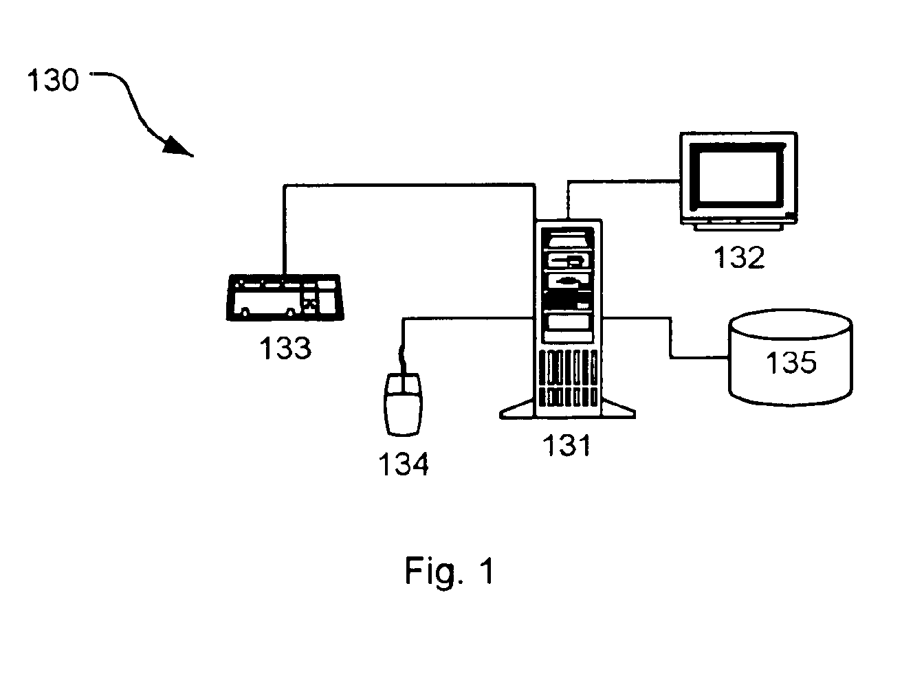
[0026]FIG. 1 shows a computerized modeling system 130 that includes a CPU 131, a CRT 132, a keyboard input device 133, a mouse input device 134, and a storage device 135. The CPU 131, CRT 132, keyboard 133, mouse 134, and storage device 135 can include commonly available computer hardware devices such as a Pentium-based computer. The mouse 134 has conventional left and right buttons that the user may press to issue a command to a software program being executed by the CPU 131. Other appropri...


PUM


Abstract

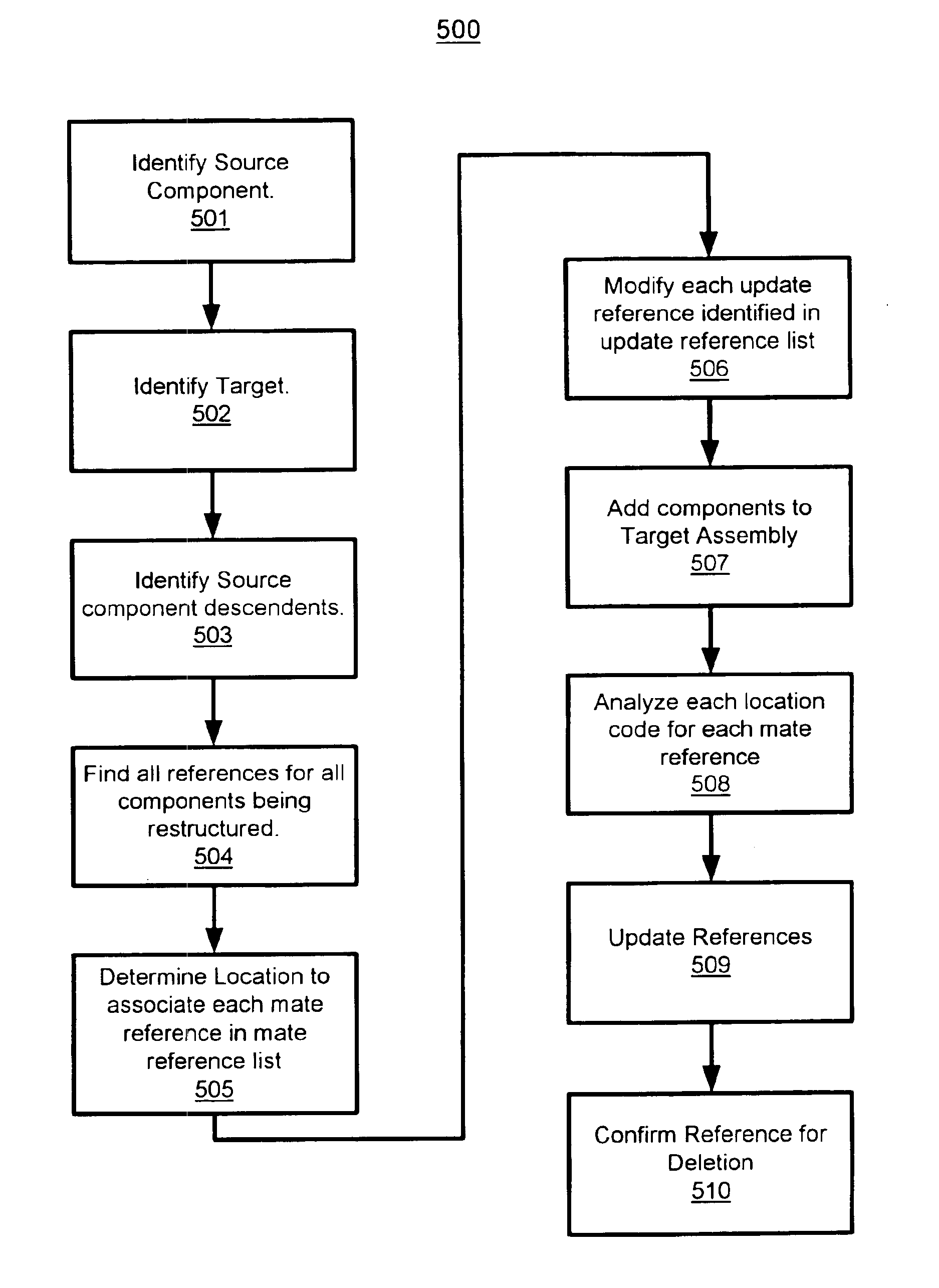
Restructuring a CAD-system generated design model includes receiving at a computer a command to restructure the design model. The command to restructure indicates a desired change in a hierarchical relationship of a first subset of the model's components with respect to other model components. In accordance with the command to restructure, a new hierarchical data structure can be generated. The new hierarchical data structure identifies a new hierarchical relationship between the model components. Other relationships that are changed as a result of the command to restructure are also determined and are automatically preserved subsequent to the generation of the new hierarchical relationship.

Description

CROSS REFERENCE TO RELATED APPLICATIONS[0001]This application claims priority to U.S. Provisional Application No. 60 / 137,233 filed Jun. 2, 1999.BACKGROUND OF THE INVENTION[0002]Computer-aided design (CAD) software allows a user to construct and manipulate models of complex three-dimensional (3D) designs of objects. A number of different modeling techniques can be used to express an object's design. These techniques include solid modeling, wire-frame modeling, and parametric modeling. Solid modeling techniques provide for a topology and surface connectivity-based modeling paradigm. Solid modeling techniques support modeling of 3D objects as collections of interconnected edges, faces, and surfaces. Wire-frame modeling techniques, on the other hand, can be used to represent a model as a simple line drawing. Wire-frame modeling techniques may help provide for computer-efficient modeling of objects. Parametric solid modeling techniques allow a model designer to define parameters intercon...

Claims


Application Information

Patent Timeline
Patent Type & Authority Patents(United States)
IPC IPC(8): G06G7/48G06G7/00G06F17/50G06T17/10
CPCG06T17/10G06F17/50G06F30/00
Inventor DAS, JYOTI
Owner DASSAULT SYST SOLIDWORKS CORP
Learn More