Co-molded ladder strap

a ladder strap and co-molded technology, applied in the field of ladder straps, can solve the problems of the highest failure rate and the largest number of replacement parts ordered for warranty, and achieve the effect of high stress, desired flexibility and hardness characteristics

Inactive Publication Date: 2005-05-31
K 2 CORP
View PDF20 Cites 77 Cited by
  • Summary
  • Abstract
  • Description
  • Claims
  • Application Information

AI Technical Summary

Benefits of technology

[0009]The present invention is directed to a ladder strap and a method of making ladder straps, wherein the ladder strap is flexible enough, particularly at low temperatures, to be flexed out of the way and to be wrapped around an object, such as a part of the ankle portion of a sports boot, while also having teeth that are strong and hard enough to withstand rigorous use—for example, the high s

Problems solved by technology

It has always been a challenge in designing ladder straps to find or select one material that is strong enough to withstand the forces that will be applied to the teeth of the strap and yet produce a strap that is flexible enough to operate properly at cold temperatures without becoming brittle or cracking, and wherein the strap can be

Method used


Image

  • Co-molded ladder strap
  • Co-molded ladder strap
  • Co-molded ladder strap

Examples


first embodiment

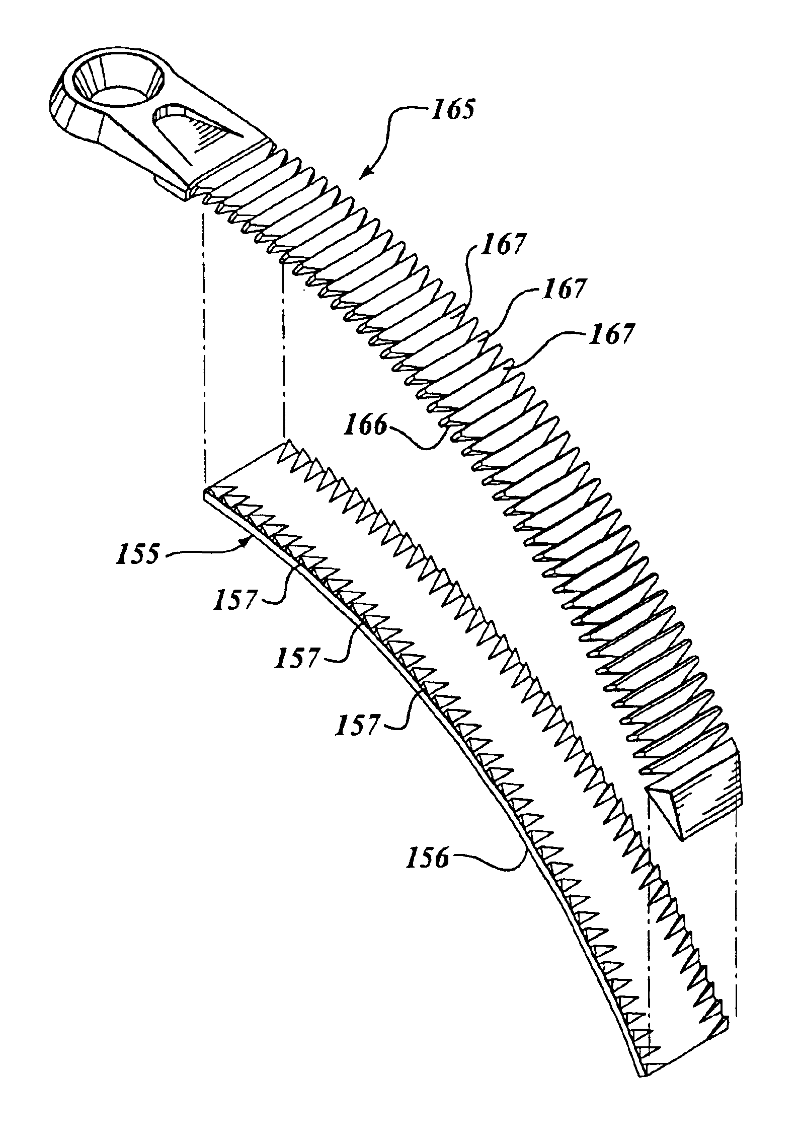
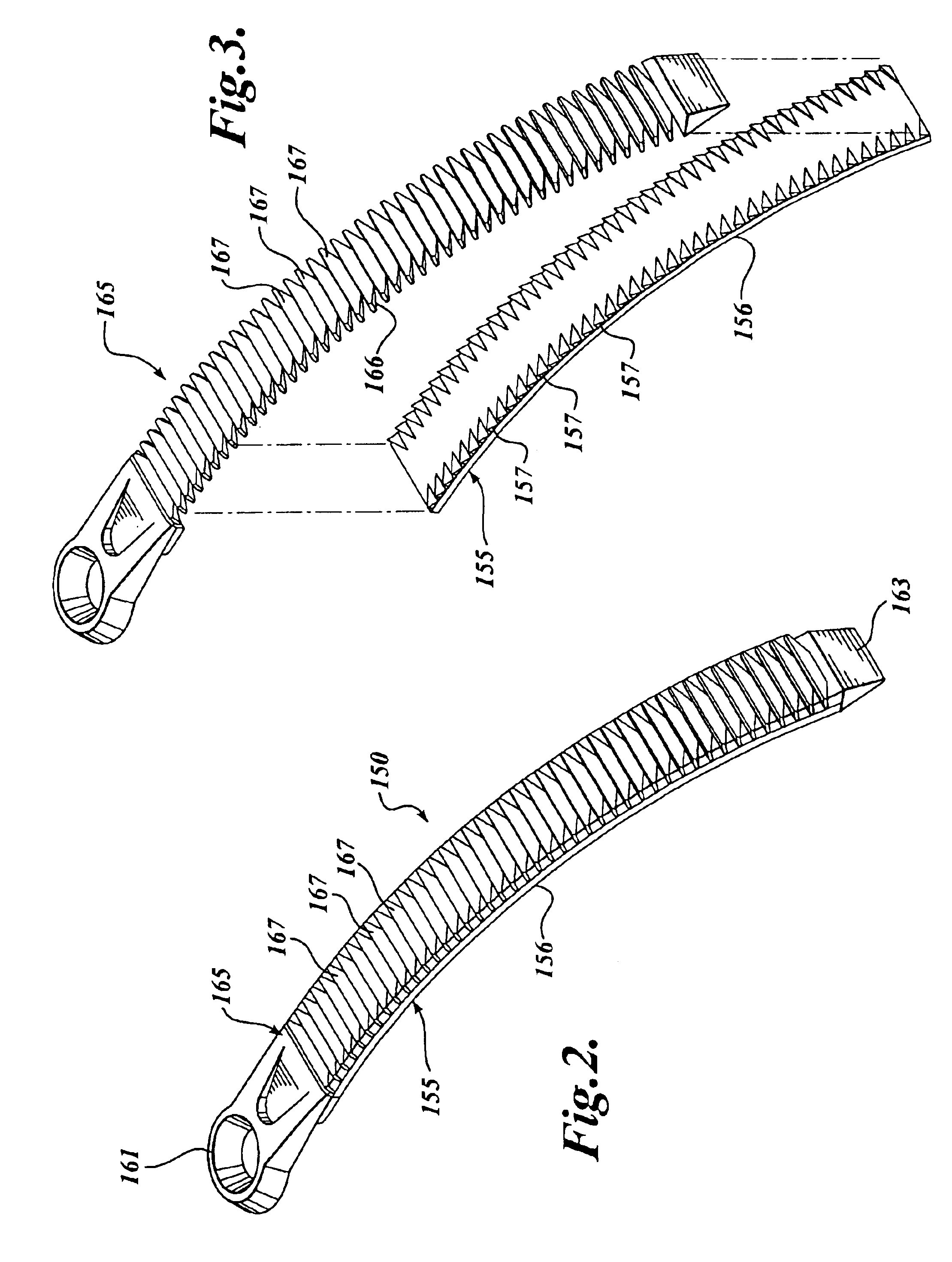
[0024]Referring now to the figures, wherein like numbers indicate like parts, a ladder strap 150 according to the present invention is shown in FIGS. 2 and 3. The ladder strap 150 includes a lower strap portion 155 having a first set of material properties and an upper strap portion 165 having a second set of material properties. The lower strap portion 155 is preferably smooth on its undersurface 156, and includes a plurality of teeth 157 on its upper surface. The teeth 157 in this embodiment are taller at the outer edges of the lower strap portion 155 and taper inwardly. The lower strap portion 155 is preferably a relatively soft, injectable, thermoplastic urethane (TPU), having good flexibility and strength characteristics at low temperatures.

[0025]The upper strap portion 165 has an undersurface 166 that generally conforms to the toothed upper surface 157 of the lower strap portion 155, and an upper portion having a plurality of buckle-engagement teeth 167. Referring now also to ...

second embodiment

[0030]An exploded side view of a co-molded ladder strap 250 according to the present invention is shown in FIG. 6. In this embodiment, the ladder strap 250 includes a relatively supple lower strap portion 255 and a relatively hard upper strap portion 265 that comprises basically a cover or cap over the lower strap portion 255. Again, it is to be understood that although shown in exploded view, the co-molded strap lower and upper portions 255 and 265, are molecularly bonded, and not intended to separate. It is contemplated that the upper strap portion 265 might also include inclined or vertical side wall portions (not shown) that cover the longitudinal edges of the lower strap portion 255, which edges may be tapered. The upper strap portion 265 and, in particular, the tapered side wall portions, might thereby impose a preferred curvature (not shown) on the lower strap portion 255—for example, to pre-dispose the strap to conform to the ankle portion of a snowboard boot.

[0031]The lower...


PUM


Abstract

A ladder strap (150) is made by joining—for example, by co-molding—a first, relatively supple material, defining a lower strap portion (155) with a second, relatively hard material defining an upper strap portion (165). The teeth (167) of the ladder strap are comprises substantially of the harder, second material. In a preferred embodiment, the first and second materials are thermoplastic urethanes, and the co-molding is done using an injection molding process. The co-molding process may be accomplished with co-injection, wherein the two materials are injected at about the same time, or the first material may be injected into a first mold cavity and allowed to partially set, after which the cavity is modified to accommodate the second material.

Description

FIELD OF THE INVENTION[0001]The present invention relates generally to straps for sports equipment and, in particular, to ladder straps that are particularly suited for sports equipment binding.BACKGROUND OF THE INVENTION[0002]Adjustable straps are frequently used in sporting equipment, particularly footwear, to provide a releasable-yet-rugged attachment for securing a user's foot in the footwear—such as ski boots, snowboard boots, in-line skates, and the like—and / or for securing the footwear to a sports device, such as a snowboard or ski. A ubiquitous strap for such applications is the serrated strap, also commonly referred to as a “ladder strap.” A ladder strap is generally a flexible, elongate strap having a plurality of closely-spaced, transverse ridges or teeth that are adapted to engage a buckle assembly, typically a ratchet-type buckle, whereby the buckle releasably holds the strap in a tensioned condition.[0003]The teeth of a ladder strap are generally integrally formed in t...

Claims


Application Information

Patent Timeline
IPC IPC(8): A43C11/14A43C11/00A63C9/00
CPCA43C11/1486A63C9/002Y10T24/2183Y10T24/21Y10T24/4016Y10T24/4072
Inventor DRAPER, ALEXANDER D.STEERE, NIGEL BRUCE EDWARDHEINLE, KENNETH WAYNE
Owner K 2 CORP
Why Eureka
Try Eureka