Optical process unit, image generation system using the same and optical process method of the same

Inactive Publication Date: 2005-05-31
NIPPON HOSO KYOKAI
View PDF4 Cites 13 Cited by
  • Summary
  • Abstract
  • Description
  • Claims
  • Application Information

AI Technical Summary

Benefits of technology

[0017]In the conventional technology, a polarization beam splitter makes two G lights necessary for generating the normal image component and the pixel-shifted image component in segregation and the composition into a singe beam is done by using the difference of the polarization. The present invention does not use such difference of the polarization but the slight difference of the wave length selectivity for the segregation and the composition. For this purpose, dichroic mirrors alter the polarizing beam splitters which have been used in the conventional technology. The prese

Problems solved by technology

In other words, it is not possible to keep the compatibility between the G pixel-shifted image processing techno

Method used


Image

  • Optical process unit, image generation system using the same and optical process method of the same
  • Optical process unit, image generation system using the same and optical process method of the same
  • Optical process unit, image generation system using the same and optical process method of the same

Examples


first embodiment

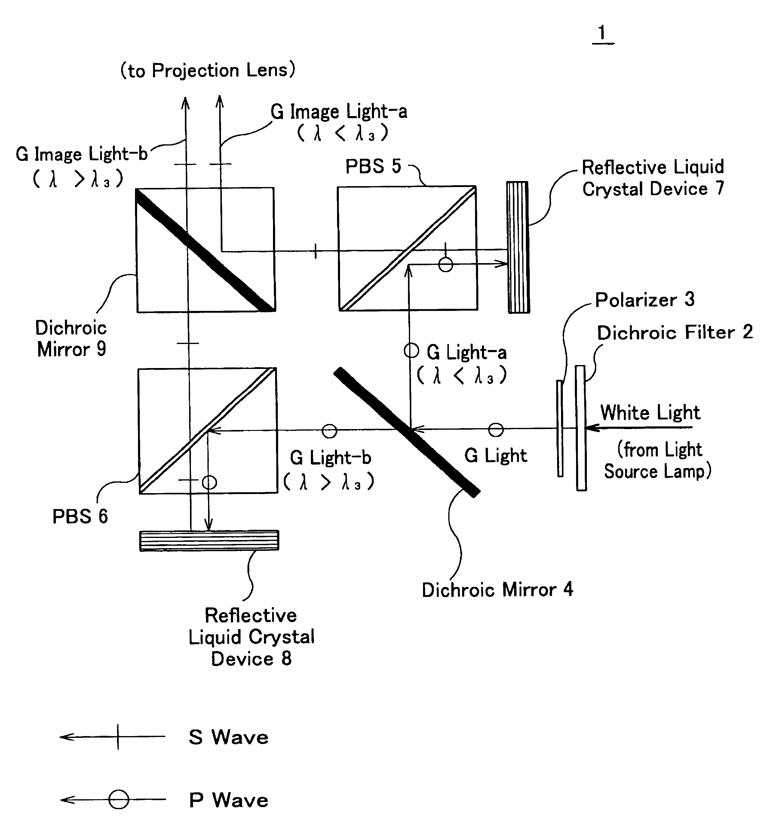
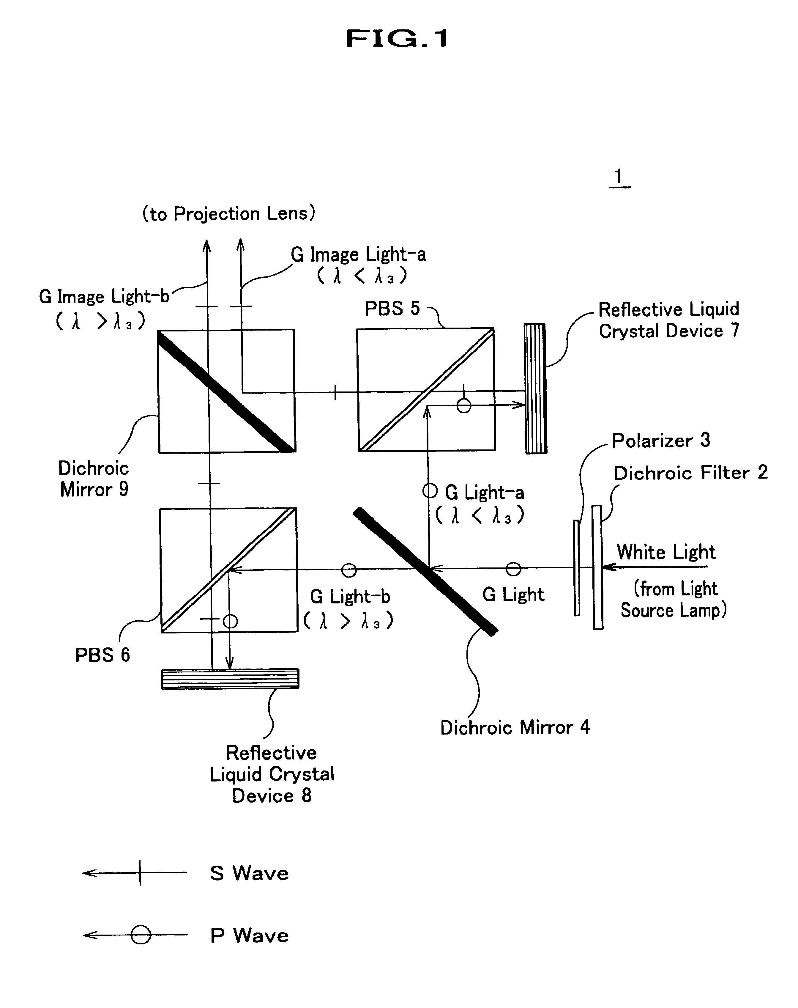
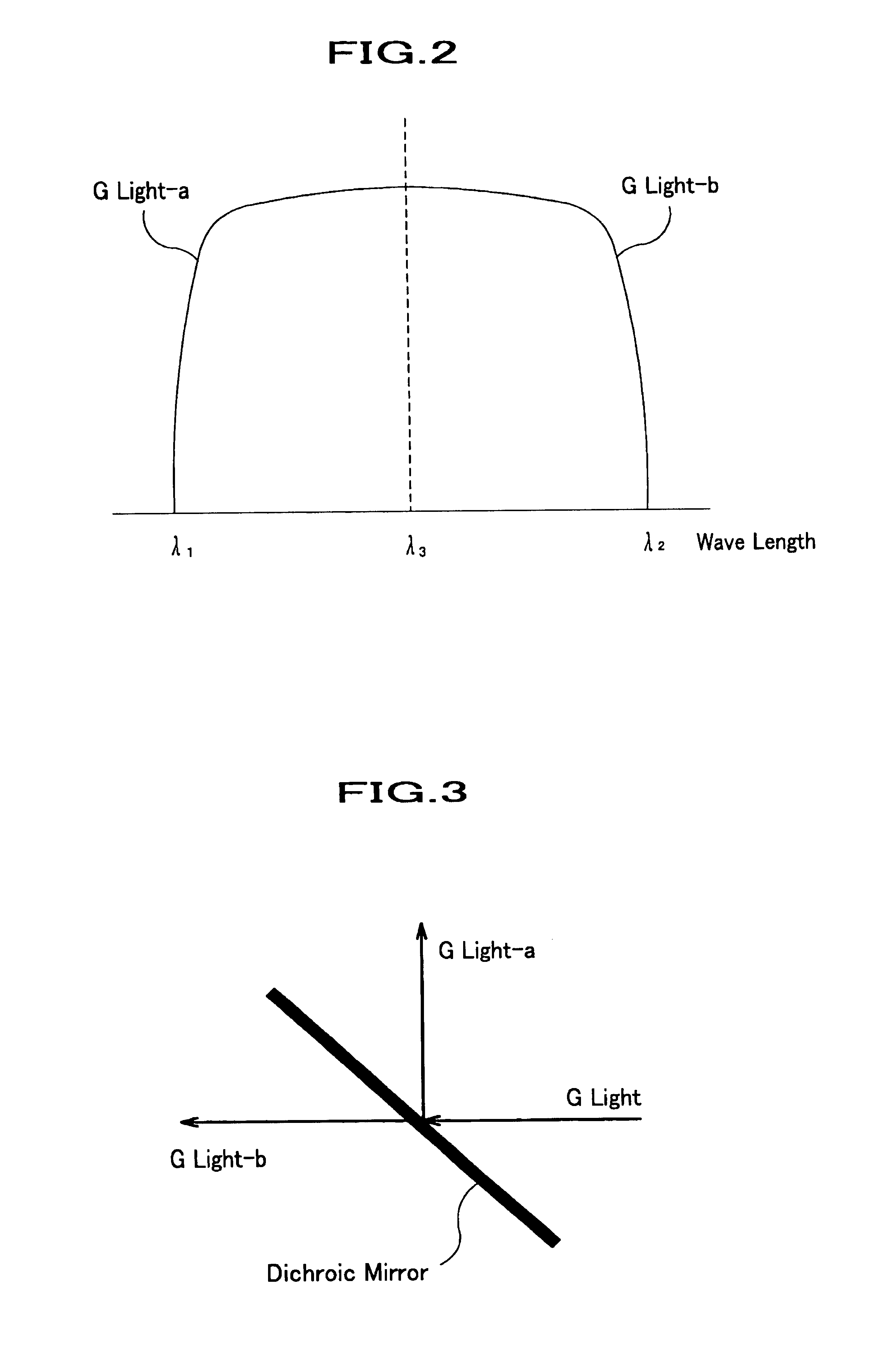
[0036]The optical process unit 1 in the first embodiment is explained using the FIGS. 1 to 3. FIG. 1 is a block diagram that shows the construction of the optical process unit according to the present invention. FIG. 2 shows an explanatory schematic of the spectrum of the green-color light, where the green-color light has a range of the wave length from λ1 at the lower limit to λ2 at the upper limit with λ3 at the central wave length. FIG. 3 schematically shows G light can be divided into a reflected G light and a transmitting G light by a dichroic mirror, provided the incident light is polarized in parallel to the surface of the dichroic mirror. The dichroic mirror reflects a light that has a certain range of the wave length and passes another light that has another range of wave length.

[0037]The optical process unit as shown in FIG. 1 comprises a G dichroic filter 2 (a filtering means), a polarizer 3 (a linear polarizing means) that selects G light of which polarization direction ...

second embodiment

[0057]The second embodiment of the present invention is a stereo image generation system 40 as shown in FIG. 5, which is a schematic thereof. The stereo image display system comprises RB projection devices 52 for the right eyes and the left eyes, G projection devices for the right eyes and the left eyes, half wave length plates (for changing polarization) and a screen 43.

[0058]The RB projection device 52 projects R image light and B image light to the screen, wherein these two image lights are in the same polarization and composed in a single image light. The linearly polarization method used in the RB projection device 52 is same as the conventional technology as described in BACKGROUND OF INVENTION with FIG. 7. The half wave length plates 41 are for rotating a linearly polarized incidental light in 90 degree. The half wave length plate is used one of two RB projection devices and one of two G projection devices so that the use of the half wave length plates to these projection dev...


PUM


Abstract

An optical processing unit comprises a dichroic filter to filtrate a green-colored light off a white light, a polarizer to selects a certain linearly polarized light component from the filtrated green-color light and a dichroic mirror to resolve the light into two lights as the first light beam and the second light beam divided at a predetermined wave length, two beam splitters to change the propagation direction of the light beams, liquid crystal devices to reflect the light beams thereon, reflective image superimposing devices to superimpose image information in the reflection onto two image lights and a dichroic mirror to compose these two image lights into an identically single image light which directs toward a direction in a single optical axis. This invention can provide an optical process unit that realizes a high fidelity stereo image display system wherein the pixel-shifted image generation and the stereo image display are compatible.

Description

FIELD OF THE INVENTION[0001]The present invention relates to an optical process unit for image display apparatus further specifically to an optical process unit of a high definition image generation device that can be used for a stereoscopic image display and a method of optical process realizing the high definition stereoscopic image display.BACKGROUND OF INVENTION[0002]As a conventional technology to realize a high definition stereo image display, a green-color pixel shifting method as described in the following paragraph has been proposed. As for a stereoscopic viewing technology, polarizing glasses are well-known for a polarized dual-view stereo display to realize such stereo image display.[0003]To begin with, a conventional display apparatus using the green-color pixel shifting method will be explained by using the FIG. 6. FIG. 6 shows a schematic that shows a display system 50 based on the technology used for the conventional display apparatus. The display system comprises an ...

Claims


Application Information

Patent Timeline
IPC IPC(8): G03B21/14G02B27/28G02B30/25H04N13/04
CPCG03B21/14G03B21/006G03B21/2073G03B33/12G03B35/20G03B35/26
Inventor HAMADA, KOICHIKANAZAWA, MASARUOKANO, FUMIO
Owner NIPPON HOSO KYOKAI
Why Eureka
Try Eureka