[0005]The present invention is based partially upon the realization that a less commonly utilized universal joint
assembly, a ring-type joint, alleviates many of the problems associated with cruciform-type joints. Like cruciform type joints, ring-type joints are utilized to pivotally interconnect yoke members (e.g., U-shaped) attached to the ends of first and second shafts. However, as opposed to utilizing a connecting member that extends between the open ends of the yokes, the ring-type joint utilizes an annular connecting member that surrounds the yoke members and receives torque transfer elements that extend radially outward from the yokes. Due to their annular geometry, ring-type universal joints allow for an increased
range of movement between the rotational axes of two interconnected shafts while reducing vibration. Additionally, ring-type joints eliminate the
stress concentration problem associated with cruciform-type joints allowing for increased load transfer between interconnected shafts.
[0008]The first and second structures of the adapter are rigidly interconnected such that rotation of the first structure (i.e., when interconnected to the yoke member) causes like rotation in the second structure. However, the first and second structures may be separately formed pieces. As will be appreciated, separately forming the first and second structures may allow added flexibility in interconnecting a plurality of differently sized yokes to a plurality of different sized ring-type universal joints. Alternatively, the first and second structures may be an integrally formed one-
piece unit. In any case, the first and second structures will typically be centered about a common axis of rotation for balance purposes. Furthermore, upon
interconnection of the first structure to an existing yoke member, the common axis of rotation will typically be aligned with the axis of rotation of the yoke member.
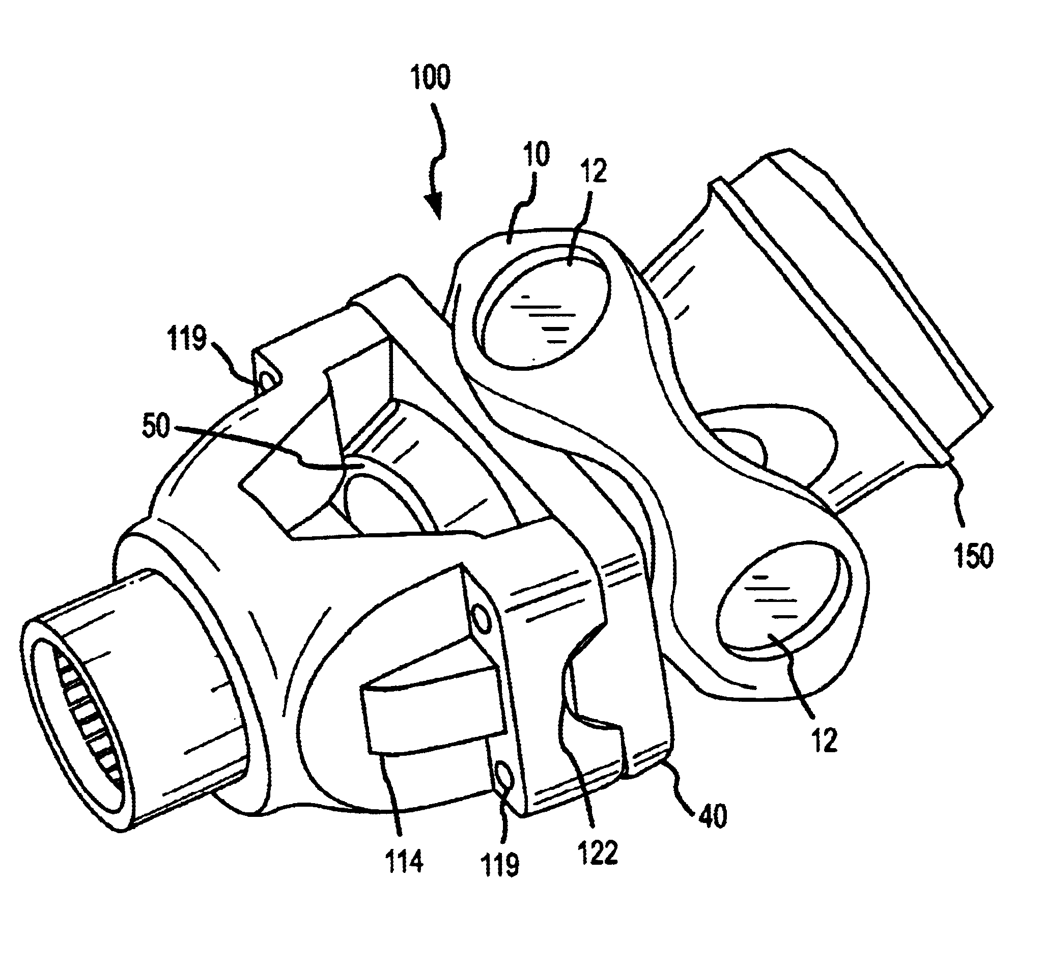
[0012]To enhance torque transfer between the yoke member and the adapter, the first structure may further include one or more torque transfer elements sized for
receipt within the opposing radial bores at least partially defined by the yoke member. For example, when
interfacing with a split yoke member that defines one-half of first and second opposing radial bores, two torque transfer elements on the first structure may comprise half cylindrical elements. Preferably, these torque transfer elements are integrally formed with the first structure to allow for increased
load carrying ability. Accordingly, depending upon the yoke member that the torque transfer elements on the first structure they are to engage, the size of those torque transfer elements may be varied. In this regard, the length, width,
diameter, etc. of the torque transfer elements may be sized for
mating receipt within opposing radial bores at least partially defined by the yoke.
[0019]Attaching the adapter to the existing yoke member may further include disposing protruding elements formed on the first interface surface of the adapter into the opposing radial bores which are at least partially defined by the yoke member. In this regard, these protruding elements (e.g., trunnions) may be utilized to align the adapter with the yoke member. More preferably, these protruding elements are matingly engaged with the opposing radial bores, thereby guaranteeing alignment of the adapter with the yoke as well as allowing for increased torque transfer therebetween during operation of the joint. Once aligned, the adapter may be fixedly attached to the yoke member. Preferably, the adapter is attached utilizing the attachment mechanisms that connected the torque transfer element to the yoke member, though this need not be the case.
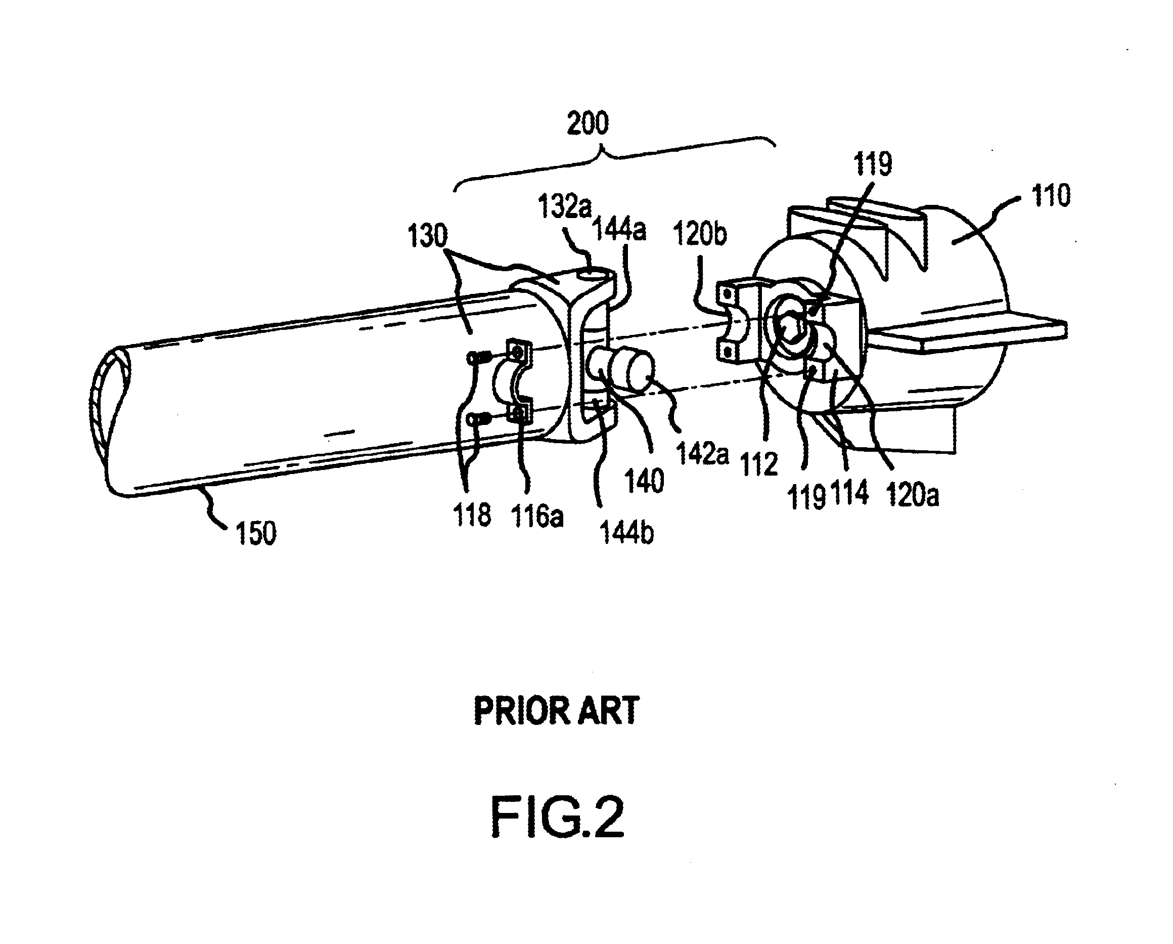
[0020]Once the adapter is interconnected to the yoke and the second interface surface is interconnected to the annular member, the annular member may be further interconnected to a second rotating member. For example, the annular member may be interconnected to a rotating shaft or to another yoke member originally designed to receive a torque transfer element between opposing radial bores. In the case where the annular member is interconnected to a shaft, the method may further include interconnecting a yoke member to the end of the shaft (e.g.,
welding) and disposing the yoke member within the aperture defined by the annular member. In any case, upon competing the steps of said method, a universal joint originally designed to receive the torque transfer member between opposing radial bores of a yoke member may be replaced by a
ring type universal joint, allowing for increased motion and / or torque transfer between rotating members




