
Apparatus for coating a substrate quickly and uniformly with a small volume of fluid

Inactive Publication Date: 2005-05-31
AGILENT TECH INC
View PDF4 Cites 44 Cited by
  • Summary
  • Abstract
  • Description
  • Claims
  • Application Information

AI Technical Summary

Benefits of technology

[0012]Accordingly, it is an object of the present invention to overcome the above-mentioned disadvantages of the prior art by providing a method for coating a substrate surface with a small volume of fluid without generating excess waste.
[0013]It is another object of the invention to provide such a method wherein the substrate is coated quickly and uniformly.

Problems solved by technology

First, the fluid may contain expensive or rare reagents, and waste of such fluids is undesirable.
Second, many ordinary reagents that are used in array preparation are toxic, and decreasing their use is desirable in order to lower the risk of human exposure.
Without uniform fluid distribution, resultant hybridization data will be compromised.
First, uniform coating requires laminar flow of the fluid.
However, pressure surges that are generated while increasing the pressure gradient tend to cause the flow cell assembly to leak, either at the cover / support interface or at the support / substrate interface.
Third, any irregularity in the surface profile of the substrate tends to disrupt laminar flow.
As a result, air pockets may be formed and trapped within the flow cell assembly that will interrupt contact between the fluid and the substrate.
Thus, while the use of a flow cell tends to lower the amount of reagent fluid waste, the gain in lowered waste is offset by diminishing throughput.
Without sufficient volume, applied fluid tends to exhibit clustering behavior and does not cover the entire surface uniformly.
Consequently, while spin coating may be advantageous in terms of high throughput, it is a relatively wasteful technique.

Method used


Image

  • Apparatus for coating a substrate quickly and uniformly with a small volume of fluid
  • Apparatus for coating a substrate quickly and uniformly with a small volume of fluid
  • Apparatus for coating a substrate quickly and uniformly with a small volume of fluid

Examples


Embodiment Construction

[0030]Before describing the invention in detail, it must be noted that, as used in this specification and the appended claims, the singular forms “a,”“an,” and “the” include plural referents unless the context clearly dictates otherwise. Thus, for example, reference to “a fluid” includes more than one fluid, reference to “a biomolecule” includes a plurality of biomolecules, reference to “a fluid source” includes a plurality of fluid sources and the like.

[0031]In describing and claiming the present invention, the following terminology will be used in accordance with the definitions set out below.

[0032]The terms “array” is used herein to refer to an ordered pattern of features, typically but not necessarily biomolecules, adherent to a substrate, e.g., a plurality of molecular probes bound to a substrate surface and arranged in a spatially defined and physically addressable manner. Such probes may be comprised of oligonucleotides, peptides, polypeptides, proteins, antibodies, or other ...


PUM

PropertyMeasurementUnit
Fractionaaaaaaaaaa
Fractionaaaaaaaaaa
Timeaaaaaaaaaa

Abstract

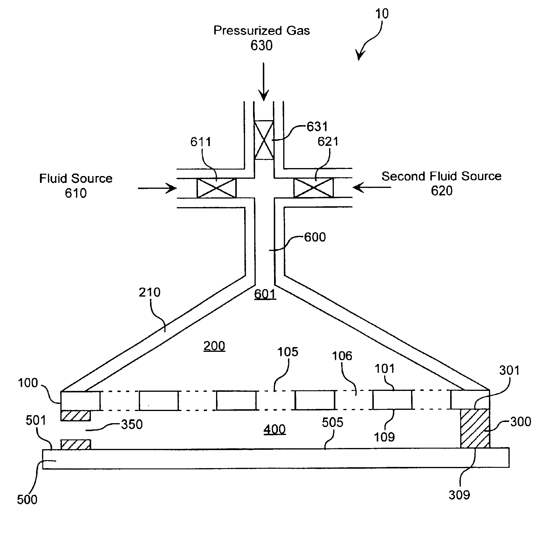
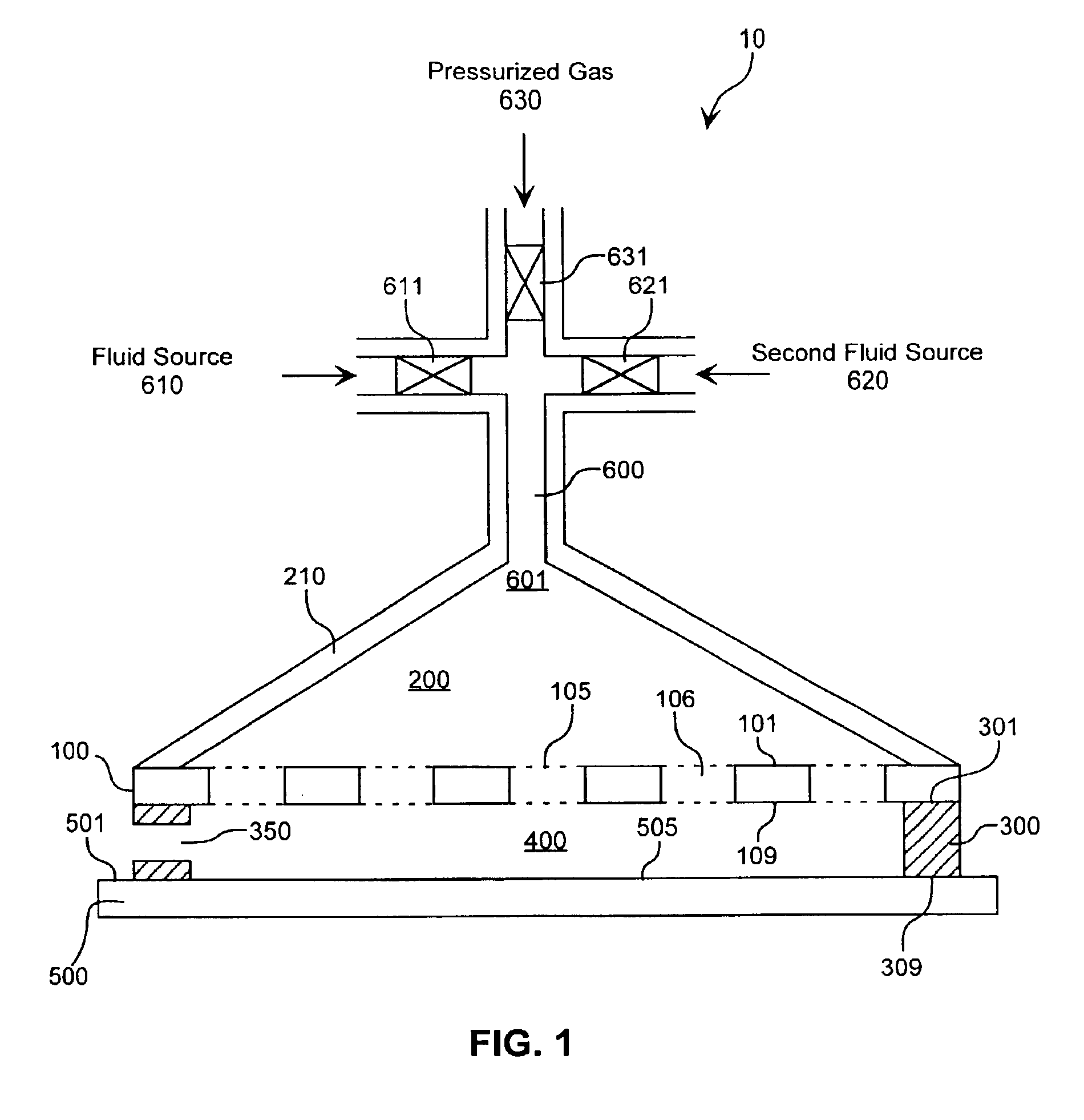
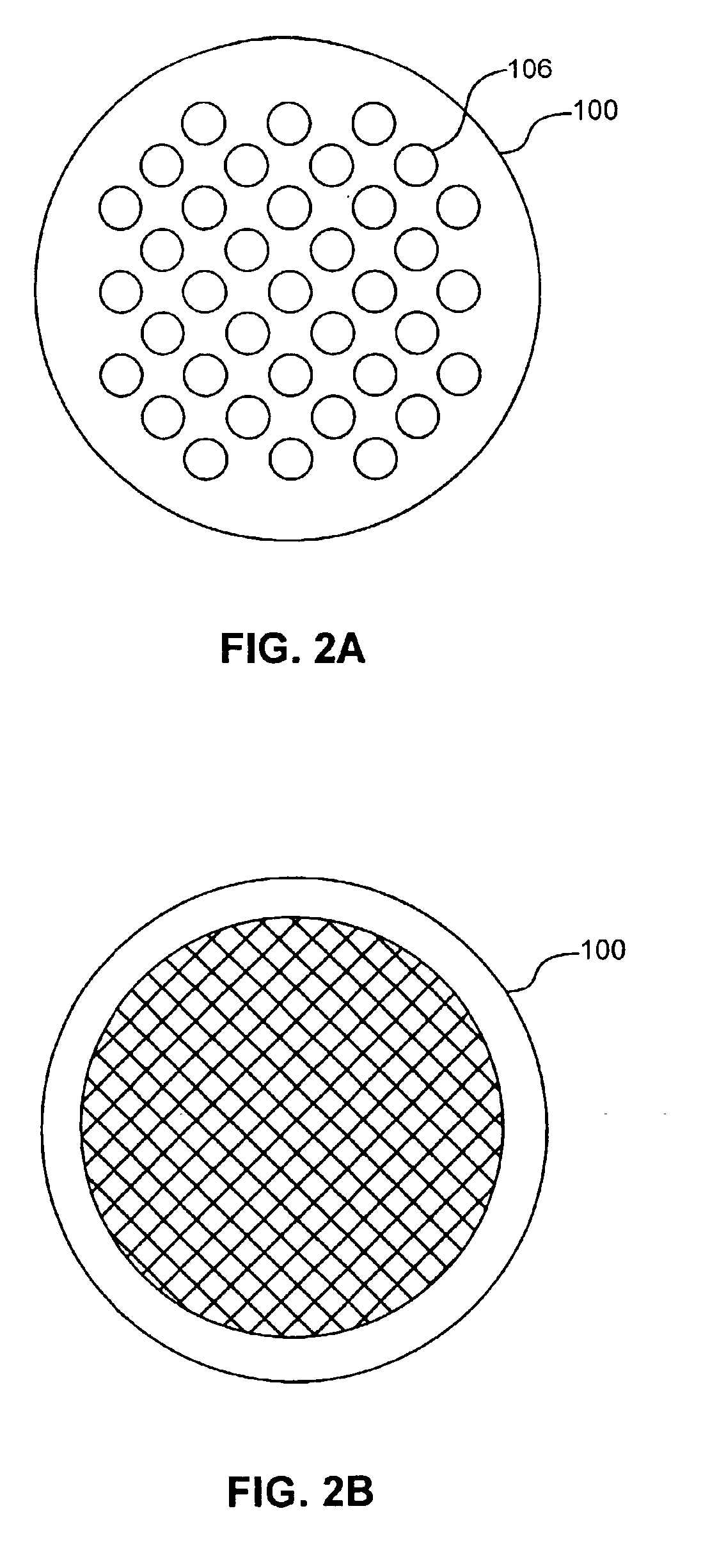
A method is provided for applying a fluid onto a surface of a solid substrate. The method employs a distribution member having an upper surface and a lower surface, and including a permeable portion having channels therethough. The distribution member is positioned such that the lower surface of the distribution member is in opposing relation to the surface of the substrate. Once the distribution member is in position, the fluid is dispensed onto the upper surface of the permeable portion of the distribution member such that the fluid penetrates the distribution member and is retained thereby. In addition, a distribution pressure differential is applied between the upper and lower surfaces without using mechanical means such as a squeegee so that a portion of the fluid passes through the channels of the permeable portion of the distribution member and onto the solid substrate surface. Other embodiments of the invention include an apparatus for carrying out the aforementioned method and a reagent application station for applying a plurality of reagents onto a surface of a solid substrate.

Description

[0001]This is a Divisional of application Ser. No. 09 / 494,187, filed on Jan. 28, 2002 now U.S. Pat. No. 6,406,851 B1, the entire disclosure of which is incorporated herein by reference.TECHNICAL FIELD[0002]This invention relates generally to a method and apparatus to coat a substrate with a small volume of fluid. More particularly, the invention relates to a method and apparatus to quickly and uniformly coat a fluid such as reagents or fluids used in DNA array fabrication onto a surface of a solid substrate by providing a pressure differential between substantially parallel surface of a fluid-containing distribution member.BACKGROUND[0003]Nucleic acid hybridization is a known method for identifying specific sequences of nucleic acids; hybridization involves base-pairing between complementary nucleic acid strands. When single-stranded nucleic acids are used as probes to identify specific target sequences of nucleic acids, probes of known sequences are exposed to and incubated in samp...

Claims


Application Information

Patent Timeline
IPC IPC(8): B05D1/26C07K17/00B01L11/00B01L99/00C40B60/14
CPCC07K17/00B05D1/26B01J2219/00351B01J2219/0036B01J2219/00418B01L3/0293Y10S530/81C40B60/14Y10S530/812
Inventor BASS, JAY K.
Owner AGILENT TECH INC
Learn More