Production process for highly conductive graphitic films

a graphitic film, highly conductive technology, applied in the direction of shielding materials, transportation and packaging, coatings, etc., to achieve the effect of improving the in-plane properties of the film and reducing the thickness of the film

Active Publication Date: 2015-09-24
GLOBAL GRAPHENE GRP INC
View PDF4 Cites 68 Cited by
  • Summary
  • Abstract
  • Description
  • Claims
  • Application Information

AI Technical Summary

Benefits of technology

[0036]Preferably, the process further comprises a step of compressing the carbonized composite film during or after the step (c) of carbonizing the precursor polymer composite film (e.g. via roll-pressing). In another preferred embodiment, the process further comprise a step of compressing the graphitic film during or after the step (d) of thermally treating the carbonized composite film to reduce the thickness of the film and improve in-plane properties of the film.

Problems solved by technology

These systems require shielding against EMI from external sources, and these systems can be sources of electromagnetic interference to other sensitive electronic devices and must be shielded.
Further, as new and more powerful chip designs and light-emitting diode (LED) systems are introduced, they consume more power and generate more heat.
This has made thermal management a crucial issue in today's high performance systems.
This further increases the difficulty of thermal dissipation.
Actually, thermal management challenges are now widely recognized as the key barriers to industry's ability to provide continued improvements in device and system performance.
Typically, heat transfer between a solid surface and the air is the least efficient within the system, and the solid-air interface thus represents the greatest barrier for heat dissipation.
However, there are several major drawbacks or limitations associated with the use of metallic heat sinks.
One drawback relates to the relatively low thermal conductivity of a metal (<400 W / mK for Cu and 80-200 W / mK for Al alloy).
In addition, the use of copper or aluminum heat sinks can present a problem because of the weight of the metal, particularly when the heating area is significantly smaller than that of the heat sink.
If metallic heat sinks are employed, the sheer weight of the metal on the board can increase the chances of the board cracking or of other undesirable effects, and increases the weight of the component itself.
Many metals do not exhibit a high surface thermal emissivity and thus do not effectively dissipate heat through the radiation mechanism.
By impregnating the exfoliated graphite with a resin, the resulting composite exhibits an even lower thermal conductivity (typically (2) Flexible graphite foils, without a resin impregnated therein or coated thereon, are of low strength, low rigidity, and poor structural integrity.
The high tendency for flexible graphite foils to get torn apart makes them difficult to handle in the process of making a heat sink.
As a matter of fact, the flexible graphite sheets (typically 50-200 μm thick) are so “flexible” that they are not sufficiently rigid to make a fin component material for a finned heat sink.(3) Another very subtle, largely ignored or overlooked, but critically important feature of FG foils is their high tendency to get flaky with graphite flakes easily coming off from FG sheet surfaces and emitting out to other parts of a microelectronic device.
These highly electrically conducting flakes (typically 1-200 μm in lateral dimensions and >100 nm in thickness) can cause internal shorting and failure of electronic devices.
3(B)), leading to relatively poor thermal conductivity, low electric conductivity, and low structural strength.
These papers or aggregates of discrete NGP, GO or RGO platelets alone (without a resin binder) also have a tendency to get flaky, emitting conductive particles into air.
Again, these aggregates have a great tendency to have graphite particles flaking and separated from the film surface, creating internal shorting problem for the electronic device containing these aggregates.
They also exhibit low thermal conductivity unless made into thin films (10 nm-300 nm, as reported by Haddon, et al) which are very difficult to handle in a real device manufacturing environment.
However, the metal matrix is too heavy and the resulting metal matrix composite does not exhibit a high thermal conductivity.
There are several major drawbacks associated with this process for producing graphitic films:(1) Technically, it is utmost challenging to maintain such an ultrahigh pressure (>100 Kg / cm2) at such an ultrahigh temperature (>2,500° C.).
The combined high temperature and high pressure conditions, even if achievable, are not cost-effective.(2) This is a difficult, slow, tedious, energy-intensive, and very expensive process.(3) This polymer graphitization process is not conducive to the production of either thick graphitic films (>50 μm) or very thin films ((4) In general, high-quality graphitic films could not be produced with a temperature lower than 2,700° C., unless when a highly oriented polymer is used as a starting material (e.g. please see Y. Nishikawa, et al.
This high degree of molecular orientation, as expressed in terms of optical birefringence, is not always possible to achieve.
Further, the use of a catalytic metal tends to contaminate the resulting graphite films with metallic elements.(5) The resulting graphitic films tend to be brittle and of low mechanical strength.
This entails a thermo-mechanical treatment of combined mechanical compression and ultra-high temperature for an extended period of time in a protective atmosphere; a very expensive, energy-intensive, and technically challenging process.
The process requires ultra-high temperature equipment (with high vacuum, high pressure, or high compression provision) that is not only very expensive to make but also very expensive and difficult to maintain.

Method used


Image

  • Production process for highly conductive graphitic films
  • Production process for highly conductive graphitic films
  • Production process for highly conductive graphitic films

Examples


example 1

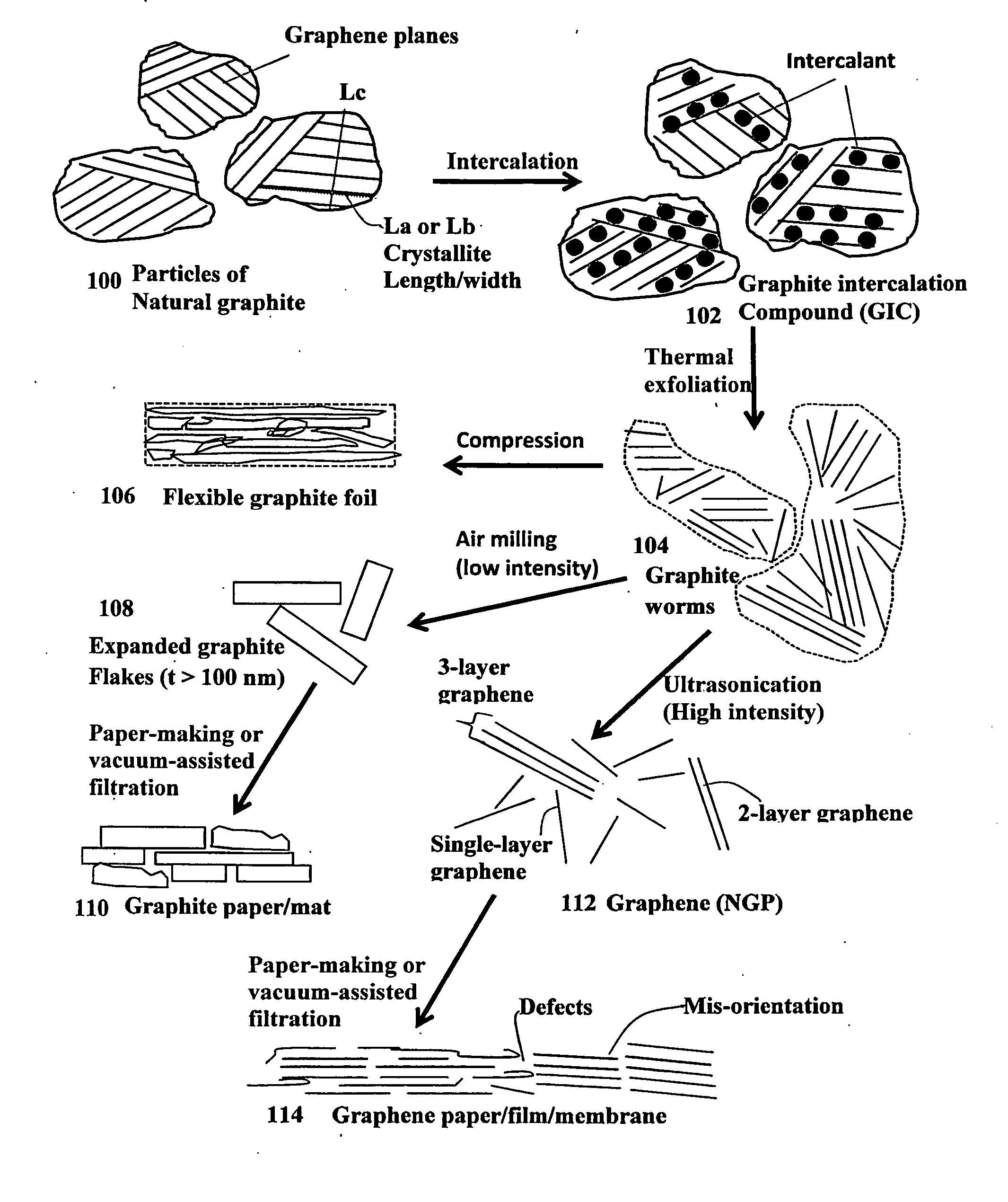
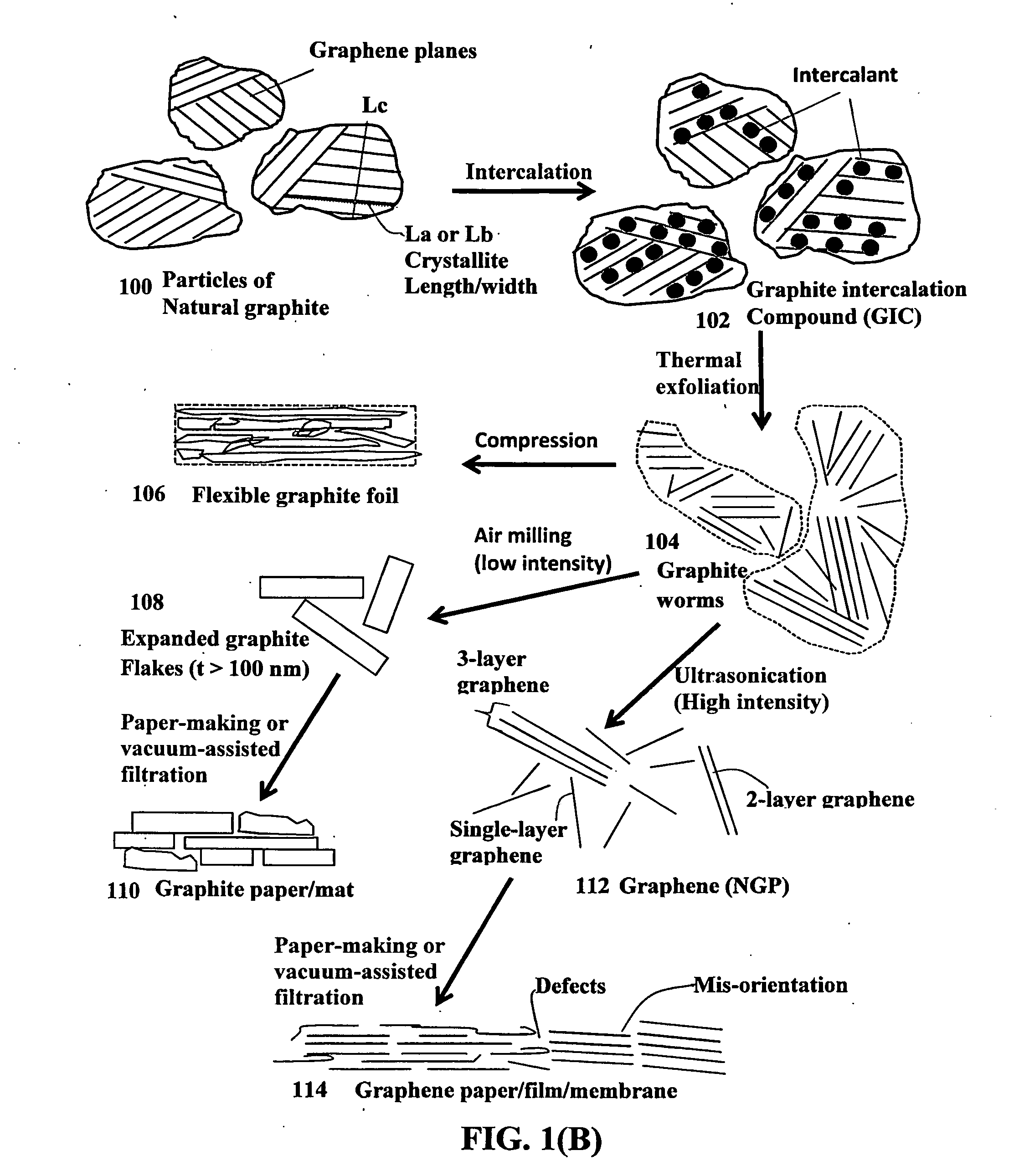
Preparation of Discrete Nano Graphene Platelets (NGPs) and Expanded Graphite Flakes

[0085]Natural graphite powder with an average lateral dimension of 45 μm was used as a starting material, which was immersed in a mixture of concentrated sulfuric acid, nitric acid, and potassium permanganate (as the chemical intercalate and oxidizer) to prepare graphite intercalation compounds (GICs). The starting material was first dried in a vacuum oven for 24 h at 80° C. Then, a mixture of concentrated sulfuric acid, fuming nitric acid, and potassium permanganate (at a weight ratio of 4:1:0.05) was slowly added, under appropriate cooling and stirring, to a three-neck flask containing fiber segments. After 16 hours of reaction, the acid-treated natural graphite particles were filtered and washed thoroughly with deionized water until the pH level of the solution reached 4.0. After being dried at 100° C. overnight, the resulting graphite intercalation compound (GIC) was subjected to a thermal shock a...

example 2

Preparation of Single-Layer Graphene Sheets from Meso-Carbon Micro-Beads (MCMBs)

[0088]Meso-carbon microbeads (MCMBs) were supplied from China Steel Chemical Co. This material has a density of about 2.24 g / cm3 with a median particle size of about 16 μm. MCMB (10 grams) were intercalated with an acid solution (sulfuric acid, nitric acid, and potassium permanganate at a ratio of 4:1:0.05) for 72 hours. Upon completion of the reaction, the mixture was poured into deionized water and filtered. The intercalated MCMBs were repeatedly washed in a 5% solution of HCl to remove most of the sulphate ions. The sample was then washed repeatedly with deionized water until the pH of the filtrate was neutral. The slurry was dried and stored in a vacuum oven at 60° C. for 24 hours. The dried powder sample was placed in a quartz tube and inserted into a horizontal tube furnace pre-set at a desired temperature, 1,080° C. for 45 seconds to obtain a graphene material. TEM and atomic force microscopic stu...

example 3

Preparation of Pristine Graphene Sheets / Platelets

[0089]In a typical procedure, five grams of graphite flakes, ground to approximately 20 μm or less in sizes, were dispersed in 1,000 mL of deionized water (containing 0.1% by weight of a dispersing agent, Zonyl® FSO from DuPont) to obtain a suspension. An ultrasonic energy level of 85 W (Branson 5450 Ultrasonicator) was used for exfoliation, separation, and size reduction of graphene sheets for a period of 15 minutes to 2 hours.


PUM

PropertyMeasurementUnit
weight fractionaaaaaaaaaa
temperatureaaaaaaaaaa

Abstract

A process for producing a graphitic film comprising the steps of (a) mixing graphene platelets with a carbon precursor polymer and a liquid to form a slurry and forming the slurry into a wet film under the influence of an orientation-inducing stress field to align the graphene platelets on a solid substrate; (b) removing the liquid to form a precursor polymer composite film wherein the graphene platelets occupy a weight fraction of 1% to 99%; (c) carbonizing the precursor polymer composite film at a carbonization temperature of at least 300° C. to obtain a carbonized composite film; and (d) thermally treating the carbonized composite film at a final graphitization temperature higher than 1,500° C. to obtain the graphitic film. Preferably, the carbon precursor polymer is selected from the group consisting of polyimide, polyamide, polyoxadiazole, polybenzoxazole, polybenzobisoxazole, polythiazole, polybenzothiazole, polybenzobisthiazole, poly(p-phenylene vinylene), polybenzimidazole, polybenzobisimidazole, and combinations thereof.

Description

FIELD OF THE INVENTION[0001]The present invention relates generally to the field of graphitic materials for electromagnetic interference (EMI) shielding and heat dissipation applications and, more particularly, to an electrically and thermally conductive graphitic film obtained from a graphene-filled polymer or carbon precursor. This graphene-polymer composite-derived film exhibits a combination of exceptionally high thermal conductivity, high electrical conductivity, and high mechanical strength.BACKGROUND OF THE INVENTION[0002]Advanced EMI shielding and thermal management materials are becoming critical for today's microelectronic, photonic, and photovoltaic systems. These systems require shielding against EMI from external sources, and these systems can be sources of electromagnetic interference to other sensitive electronic devices and must be shielded. Materials for EMI shielding applications must be electrically conducting.[0003]Further, as new and more powerful chip designs a...

Claims


Application Information

Patent Timeline
Patent Type & Authority Applications(United States)
IPC IPC(8): C01B31/04H01B13/00C09K5/14
CPCC01B31/04H01B13/0026H01B13/0016C09K5/14C01B32/182C01B32/20H01B1/04Y10T428/30H05K9/0073
Inventor ZHAMU, ARUNAJANG, BOR Z.
Owner GLOBAL GRAPHENE GRP INC
Why Eureka
Try Eureka