Methods and apparatus for location determination based on dispersed radio frequency tags

a technology of radio frequency tags and methods, applied in direction finders using radio waves, instruments, reradiation, etc., can solve the problems of gps receivers not being reliable solutions for determining the location of users inside buildings, gps receivers having drawbacks that detract from their desirability, and it may take several minutes for gps receivers to achieve location fix

Inactive Publication Date: 2005-05-31
GEMPLU
View PDF11 Cites 67 Cited by
  • Summary
  • Abstract
  • Description
  • Claims
  • Application Information

AI Technical Summary

Benefits of technology

[0006]A system of wireless telephone location identification according to an aspect of the present invention employs a set of radio frequency (RF) tags dispersed throughout a building. The location of a wireless telephone or other device employing the tags for location identification is determined by receiving and processing signals received from tags in the vicinity of the device. If signals from multiple tags are employed in determining the location, it is possible to uniquely identify a location even if two or more tags from which signals are received are not unique. The reason for this is that the combination of signals received is highly likely to be unique, even if two or more individual tags are n

Problems solved by technology

Global positioning system (GPS) receivers have great value in determining the location of a user, but the use of a GPS receiver is not a reliable solution for determining the location of a user inside a building, especially in a critical application such as providing a user's location to an emergency call system.
However, even in outdoor use, GPS has drawbacks that detract from its desirability as the sole source of location information in critical situations.
A GPS receiver may take several minutes to achieve a location fix, particularly if the GPS receiver has been transported more than a few hundred miles since last achieving a loca

Method used


Image

  • Methods and apparatus for location determination based on dispersed radio frequency tags
  • Methods and apparatus for location determination based on dispersed radio frequency tags
  • Methods and apparatus for location determination based on dispersed radio frequency tags

Examples


Embodiment Construction

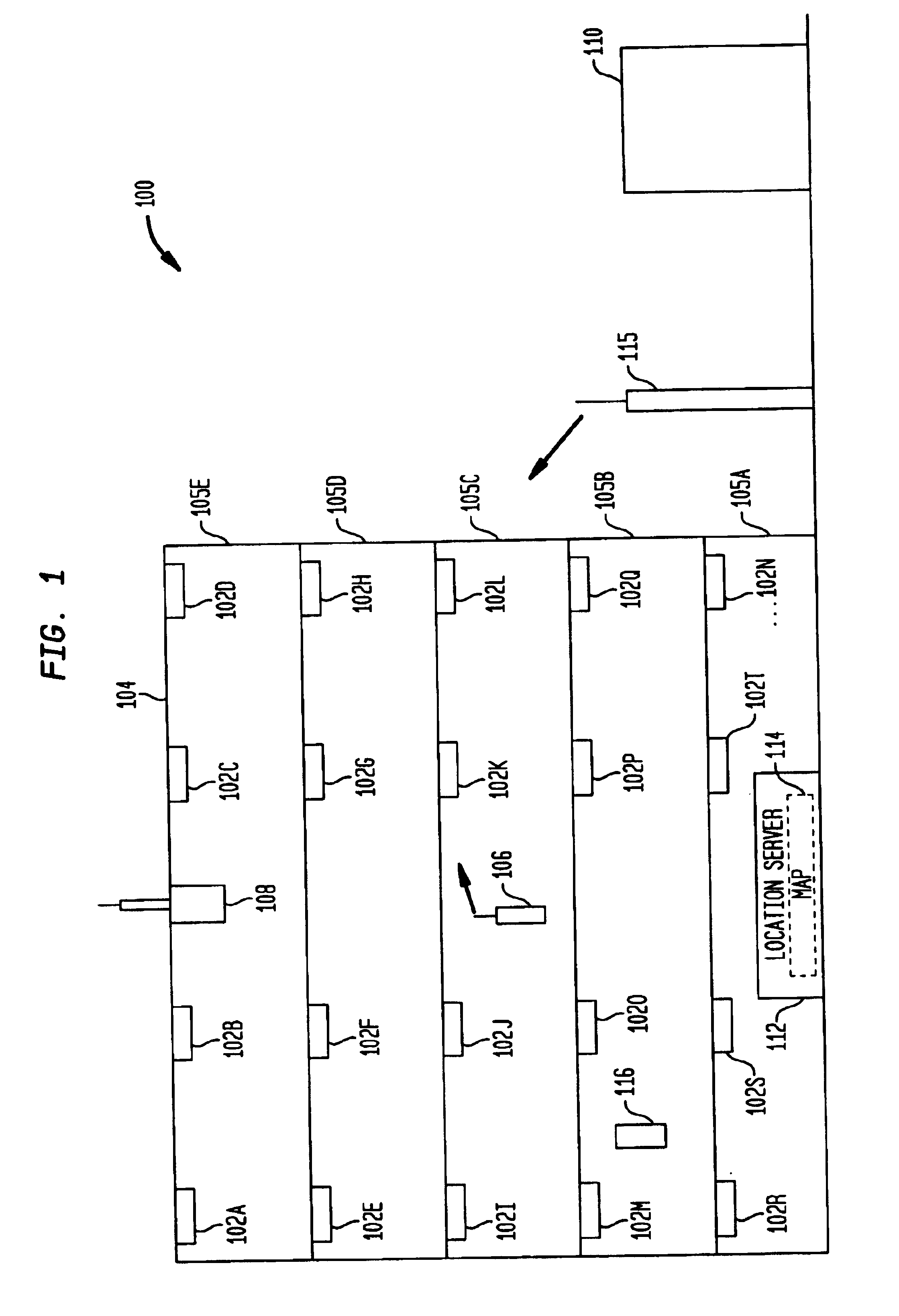
[0014]FIG. 1 illustrates a location identification system 100 according to an aspect of the present invention. The system 100 includes a plurality of identifier tags 102A . . . 102N dispersed throughout a preferably three dimensional, such as a building, within which a user's location is to be determined. In the example illustrated here, the representation of the region is a vertical layout of a building 104, showing the floors 105A-105E.

[0015]The user's location is determined by a portable device such as a wireless telephone 106 that receives signals from a nearby one or ones of the tags 102A . . . 102N, such as the tags 102J and 102K. A central location broadcaster 108 may suitably be located in the building 104, broadcasting geographic coordinates, such as address, latitude and longitude or the like in such a way that this information can be received by the telephone 106 or by any other portable devices that may need to use such information. When the user makes a call to an emerg...


PUM


Abstract

Systems and techniques for location determination. A plurality of tags emitting radio frequency signals are dispersed throughout a region, such as a building, within which a user's location is to be determined. The radio frequency signals emitted by the tags include information that can be used to identify the location in which the tags axe placed, or simply to distinguish the tags from one another. A portable device receives signals from the tags and provides the signal information to a location server that computes the location of the portable device by comparing the signal information received from the portable device to a map of location venus stored signal information, and identifies the location of the portable device as the location for which the stored signal information best matches the signal information received from the portable device.

Description

FIELD OF THE INVENTION[0001]The present invention relates generally to improved techniques for location determination. More particularly, the invention relates to techniques for determining the location of a portable device based on signals received from radio frequency tags dispersed throughout a region within which the location of the portable device is to be determined.BACKGROUND OF THE INVENTION[0002]Identifying the location of a wireless telephone making an emergency call is a matter of great importance and intense interest. Unlike a landline telephone whose telephone number is associated with a particular address, wireless telephones can be used from anywhere and knowledge of the telephone number of the wireless telephone making the call contributes nothing toward the knowledge of the location of the wireless telephone at the time of the call.[0003]Global positioning system (GPS) receivers have great value in determining the location of a user, but the use of a GPS receiver is...

Claims


Application Information

Patent Timeline
IPC IPC(8): G01S5/02G01S5/00G01S13/75G01S13/00G01S19/03
CPCG01S5/0036G01S5/02G01S13/75G01S2205/02G01S5/0295
Inventor ANDREWS, MICHAEL R.HO, TIN KAMKOCHANSKI, GREGORY P.LANZEROTTI, LOUIS J.THOMSON, DAVID J.
Owner GEMPLU
Why Eureka
Try Eureka