Method and system for measuring optical characteristics of a sub-component within a composite optical system

a composite optical system and optical characteristic technology, applied in the field of optical network analysis, can solve the problems of inability to readily determine the optical characteristics of a particular sub-component, inability to provide significant information about the individual sub-components which comprise the composite optical system, and inability to readily determine the optical characteristics of each or any individual fiber bragg grating within the composite system. achieve the effect of ensuring the optical characteristi

Inactive Publication Date: 2005-05-31
AGILENT TECH INC
View PDF5 Cites 24 Cited by
  • Summary
  • Abstract
  • Description
  • Claims
  • Application Information

AI Technical Summary

Benefits of technology

[0008]The present invention provides a method and system to readily determine the optical characteristics of a sub-component of a composite optical system. The present invention further provides for a method and system which achieves the above accomplishment and which does not require dismantling of the composite optical system. The present invention also provides a method and system which achieves the above accomplishments and which can be used to verify or correct manufacturer specified optical characteristics for a sub-component within a composite optical system. The present invention further provides a method and system which achieves the above accomplishments and which is compatible with interferometric optical component analyzers employing continuously sweeping light sources.

Problems solved by technology

Although such an approach provides information about the optical characteristics of the composite optical system, such conventional approaches do not provide significant information about the individual sub-components which comprise the composite optical system.
That is, while a conventional approach may measure, for example, the cumulative optical characteristics of a series of fiber Bragg gratings, conventional approaches do not readily provide the optical characteristics of each or any individual fiber Bragg grating within the composite system.
Although a composite optical system having multiple fiber Bragg gratings is mentioned above, the inability to readily determine the optical characteristics of a particular sub-component is relevant to numerous other types of composite optical systems and various other types of devices under test (DUTs).
While such an approach may enable distinctly determining the optical characteristics of the removed sub-component, dismantling a composite optical system can be extremely complicated and time-consuming resulting in damage to the ultimately re-assembled composite optical system.
Hence, dismantling of a composite optical system is not a viable or desired approach for measuring the optical characteristics of a sub-component within a composite optical system.
Unfortunately, such specifications may not include the optical characteristics of interest.
Moreover, in some instances, even if the optical characteristics of interest are recited for the sub-component, the manufacturer provided specifications may be inaccurate.
Hence, it is not always possible to rely upon manufacturer provided specifications to ascertain the optical characteristics of a sub-component within a composite optical system.
Such systems, however, provide analysis of the entire composite optical system and not an individual sub-component thereof.

Method used


Image

  • Method and system for measuring optical characteristics of a sub-component within a composite optical system
  • Method and system for measuring optical characteristics of a sub-component within a composite optical system
  • Method and system for measuring optical characteristics of a sub-component within a composite optical system

Examples


Embodiment Construction

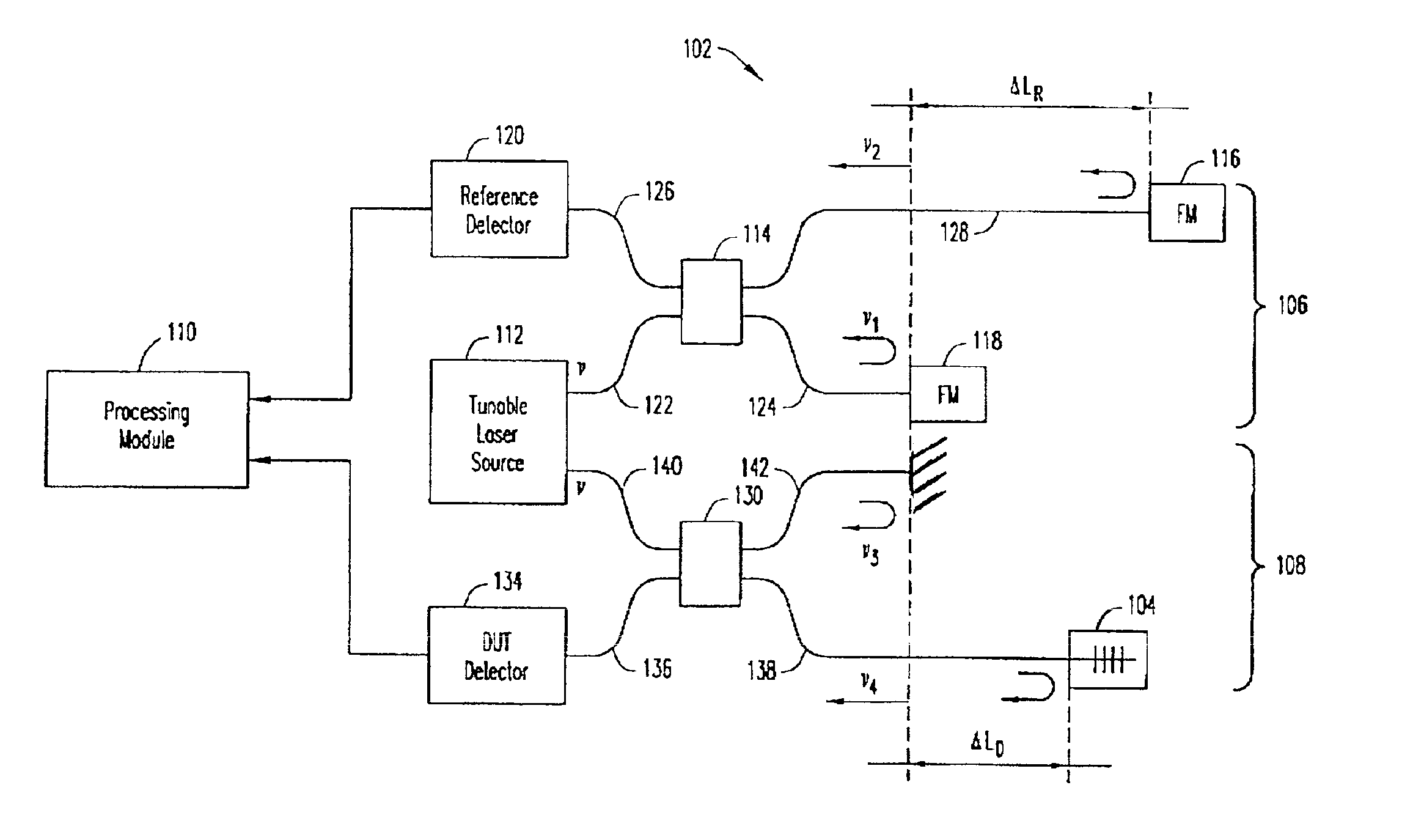
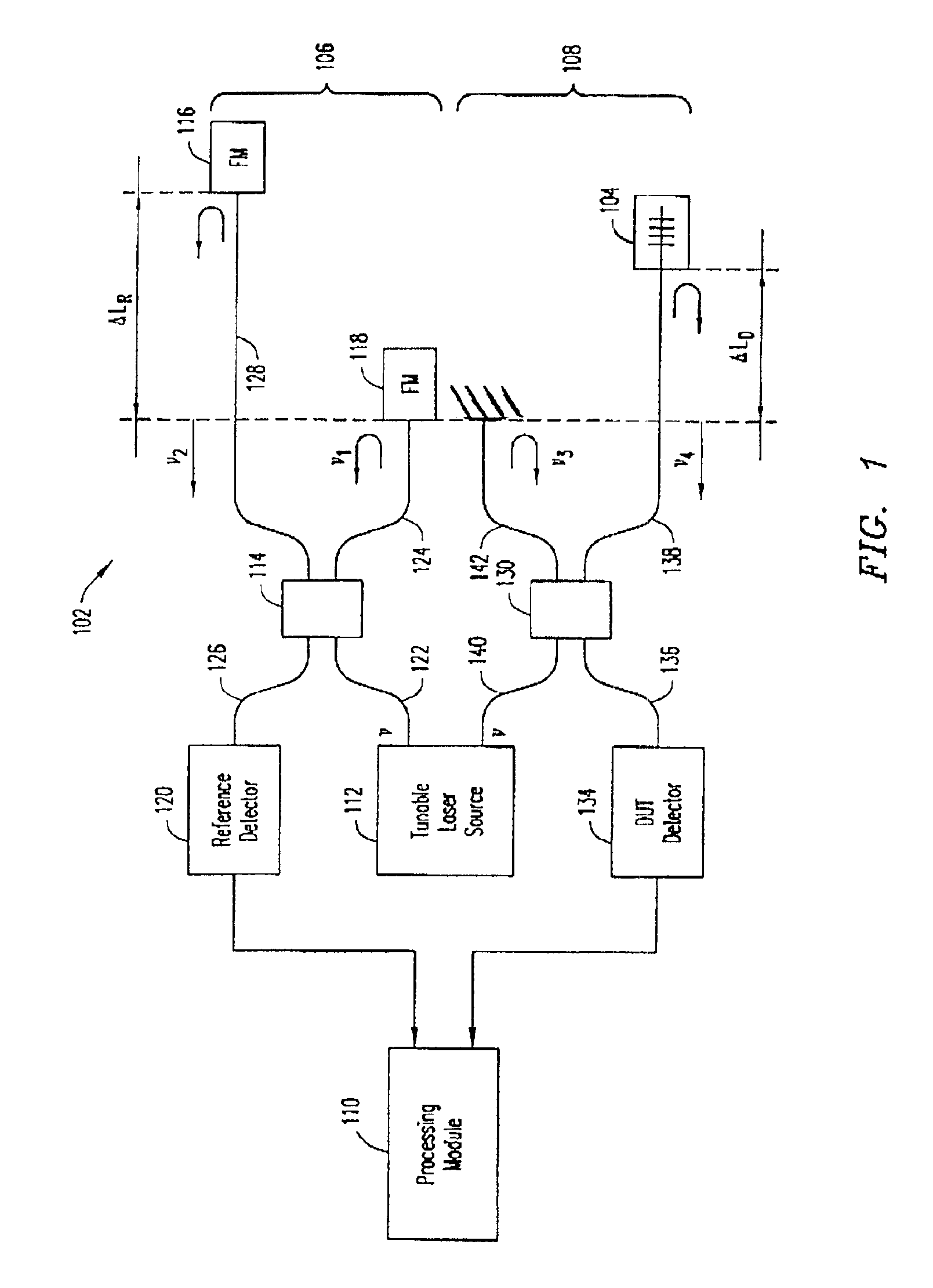
[0045]Reference will now be made in detail to the preferred embodiments of the invention, examples of which are illustrated in the accompanying drawings. While the invention will be described in conjunction with the preferred embodiments, it will be understood that they are not intended to limit the invention to these embodiments. On the contrary, the invention is intended to cover alternatives, modifications and equivalents, which may be included within the scope of the invention as defined by the appended claims. Furthermore, in the following detailed description of the present invention, numerous specific details are set forth in order to provide a thorough understanding of the present invention. However, the present invention may be practiced without these specific details. In other instances, well known methods, procedures, components, and circuits have not been described in detail as not to unnecessarily obscure aspects of the present invention.

[0046]The following discussion w...


PUM

PropertyMeasurementUnit
wavelengthaaaaaaaaaa

Abstract

A method and system for measuring optical characteristics of a sub-component within a composite optical system is disclosed. In one embodiment, the present invention generates an optical response from a composite optical system. The present embodiment then separates an optical response of a sub-component from the optical response of the composite optical system. The present embodiment then determines the optical characteristics of the sub-component by utilizing at least one portion of the optical response of the sub-component.

Description

RELATED APPLICATION[0001]This application is a Continuation-in-Part of commonly-owned, co-pending U.S. patent application entitled “Interferometric Optical Component Analyzer Based on Orthogonal Filters”, by Szafraniec et al. filed Aug. 22, 2001 and having U.S. Ser. No. 09 / 938,100 which incorporated herein by reference.TECHNICAL FIELD[0002]The present claimed invention relates to the field of optical network analysis. More specifically, the present claimed invention relates to determining the optical characteristics of an optical component.BACKGROUND ART[0003]Optical network analysis is frequently used to determine optical characteristics of a composite optical system. For example, the optical characteristics of a series of fiber Bragg gratings can be determined using an optical network analyzer. Although such an approach provides information about the optical characteristics of the composite optical system, such conventional approaches do not provide significant information about t...

Claims


Application Information

Patent Timeline
Patent Type & Authority Patents(United States)
IPC IPC(8): G01M11/00G01B9/02G01M11/02G01J9/04
CPCG01M11/3172G01B2290/60
Inventor MOTAMEDI, ALISZAFRANIEC, BOGDANVANWIGGEREN, GREGORY D.
Owner AGILENT TECH INC
Why Eureka
Try Eureka