
Fault tolerant optical amplifier configuration using pump feedthrough

a technology of optical amplifiers and feedthrough, applied in the direction of optical elements, semiconductor amplifier structures, instruments, etc., can solve the problems of increasing costs and power requirements, active components in amplifiers and are usually the most expensive,

Inactive Publication Date: 2005-05-31
TYCO TELECOMM US
View PDF10 Cites 6 Cited by
  • Summary
  • Abstract
  • Description
  • Claims
  • Application Information

AI Technical Summary

Benefits of technology

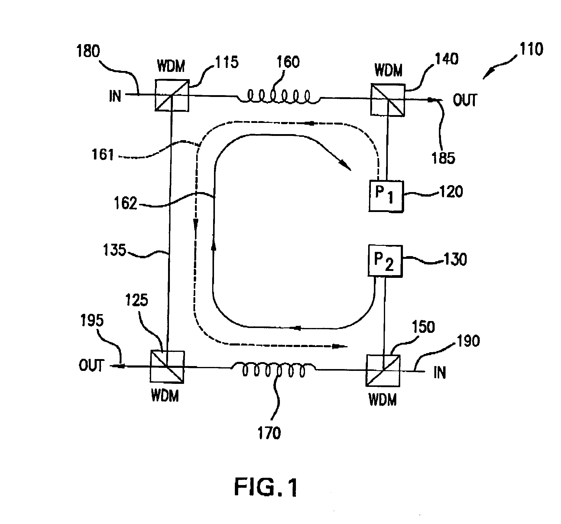
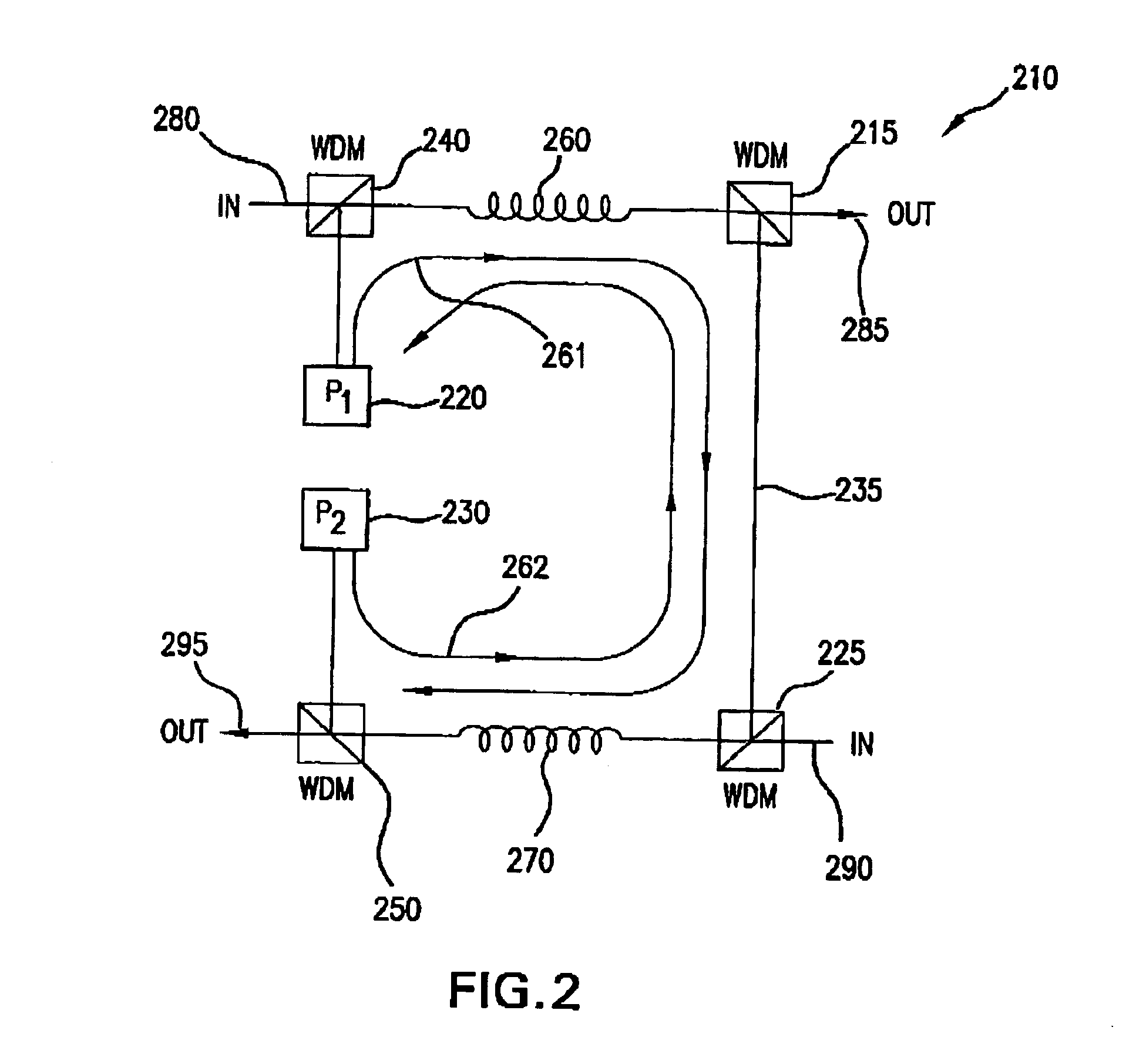
[0008]One embodiment of the invention comprises a method and apparatus that provides a fault tolerant pump source configuration in an optical amplifier. A first pump source supplies pump power to a first amplifying fiber segment for amplifying transmission signals propagating through the first fiber segment in a first direction. A second pump source supplies pump power to a second amplifying fiber segment for amplifying transmission signals propagating through the second fiber segment in a second direction. A portion of the pump signal supplied to the first amplifying fiber segment remains after propagation through the first fiber segment. This remaining feed-through signal is supplied to a second amplifying fiber segment and amplifies the transmission signals propagating through the second amplifying fiber. Likewise, a portion of the pump signal supplied to the second amplifying fiber segment remains after propagation through the second fiber segment. This remaining feed-through signal is supplied to the first amplifying fiber segment and amplifies transmission signals propagating through the first amplifying fiber. When a pump source fails, the remaining operating pump directly pumps its associated amplifying fiber segment and its feed-through signal pumps the other amplifying fiber segment associated with the failed pump source. This feed-through architecture alleviates the need for additional pump sources for pump redundancy purposes in high reliability communication systems.

Problems solved by technology

These pump sources are the only active component in the amplifier and are usually the most expensive.
However, some redundant configurations employ additional pump sources that increase costs and power requirements.

Method used


Image

  • Fault tolerant optical amplifier configuration using pump feedthrough
  • Fault tolerant optical amplifier configuration using pump feedthrough
  • Fault tolerant optical amplifier configuration using pump feedthrough

Examples


Embodiment Construction

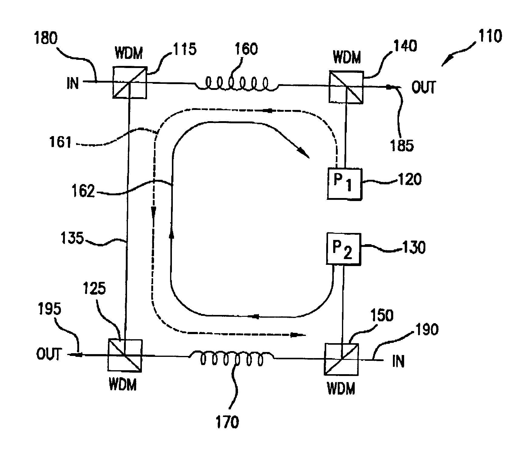
[0012]FIG. 1 schematically illustrates an exemplary configuration for amplifier pair 110 for use within an optical communication system or network. Amplifier pair 110 may be one of a plurality of amplifiers disposed along a transmission path. The amplifier pair is configured to amplify transmission signals carrying communications traffic in two directions; from input port 180 to output port 185 and from input port 190 to output port 195 (e.g. East to West and West to East). A first amplifier comprises a light pump source 120, wavelength discriminating coupler 140 (WDM coupler) and amplifying fiber segment 160. A second amplifier includes light pump source 130, wavelength discriminating coupler 150 and amplifying fiber segment 170.

[0013]The first amplifier amplifies light entering port 180 and outputted via port 185 and the second amplifier amplifies light entering port 190 and outputted via port 195. Fiber segments 160 and 170 are doped with a rare earth element, such as erbium, tha...


PUM


Abstract

A method and apparatus for amplifying optical transmission signals is described. A bi-directional amplifier utilizes a pump feed-through signal from one of the optical pumps used to pump a first amplifying fiber to provide pump power to a second amplifying fiber. If an optical pump within the amplifier fails, this feed-through signal is used to pump the amplifying fiber directly pumped by the failed pump source.

Description

CROSS REFERENCE TO RELATED APPLICATION[0001]The present application claims the benefit of U.S. Provisional Application Ser. No. 60 / 263,982, filed Jan. 25, 2001, entitled “Fault Tolerant Optical Amplifier Configuration Using Pump Feedthrough”, the teachings of which are incorporated herein by reference.FIELD OF THE INVENTION[0002]The present invention relates generally to optical fiber amplifiers and more particularly to optical fiber amplifiers having an optical pump fault tolerant capability using an optical pump feed-through configuration.BACKGROUND OF THE INVENTION[0003]Optical fiber amplifiers have been employed in telecommunication systems to amplify light transmission signals. Optical amplifiers, and more particularly erbium doped fiber amplifiers, are attractive for telecommunications systems for a number of reasons including wavelength independence and bit rate transparency.[0004]Optical amplifiers are disposed along the transmission path of an optical communication system. ...

Claims


Application Information

Patent Timeline
IPC IPC(8): H01S3/06H01S3/067H01S3/094
CPCH01S3/06754H01S3/09408H01S3/094011
Inventor NAGEL, JONATHAN A.
Owner TYCO TELECOMM US
Learn More