Method of fabricating a coil and clamp for variable reluctance transducer

a variable reluctance and coil technology, applied in the field of sensors, can solve the problems of sensitive instruments being subject to rough handling, difficult and expensive permanent instruments by hard wires to data recorders, and peaks in the resistance of such structures, so as to achieve the effect of less cost and more robustness

Inactive Publication Date: 2005-06-07
LORD CORP
View PDF21 Cites 22 Cited by
  • Summary
  • Abstract
  • Description
  • Claims
  • Application Information

AI Technical Summary

Benefits of technology

[0014]It is an advantage of the present invention that a sensor is lower cost and more robust as a result of having a surface mountable coil with a moveable coil that provides variable reluctance and a shape memory alloy clamp for holding peak displacement of the core.
[0015]These and other objects, features, and advantages of the invention are accomplished by a method of fabricating a discrete coil. The method involves providing a conductor wound in a coil on a tube. The coil has a coil outer surface. The coil outer surface has insulation. A window is opened in the insulation on the coil outer surface to expose conductor of the coil for a contact. A movable core is provided within the tube for adjusting inductance of the coil.
[0016]Another aspect the invention is also a method of fabricating a discrete coil. This method involves providing a conductor wound in a coil. The coil has a coil outer

Problems solved by technology

Strain to such structures may peak when power is not available, such as during hurricanes, tornadoes, and earthquakes.
Similarly, structures that are repeatedly stressed, such as helicopter and aircraft landing gear, and which may need to be repaired, reinforced, or replaced if strain exceeds a threshold, could benefit from strain monitoring, but these structures are difficult and expensive to permanently instrument by hard wires to a data recorder.
Sensitive instruments may also be subject to rough handling during transport, but data recorders powered by batteries may not be a practical or cost effective monitoring solution for such instruments.
However, wh

Method used


Image

  • Method of fabricating a coil and clamp for variable reluctance transducer
  • Method of fabricating a coil and clamp for variable reluctance transducer
  • Method of fabricating a coil and clamp for variable reluctance transducer

Examples


Embodiment Construction

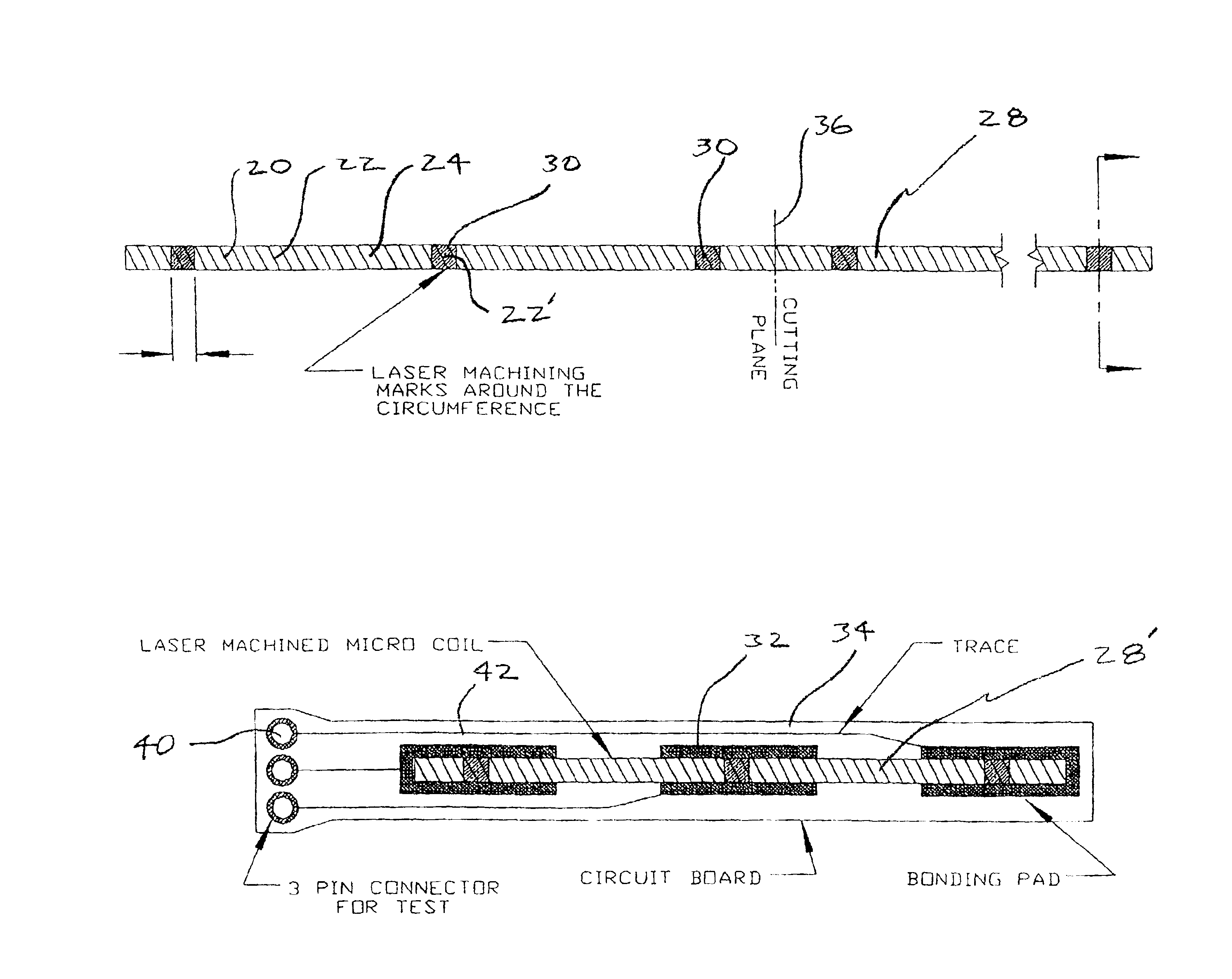
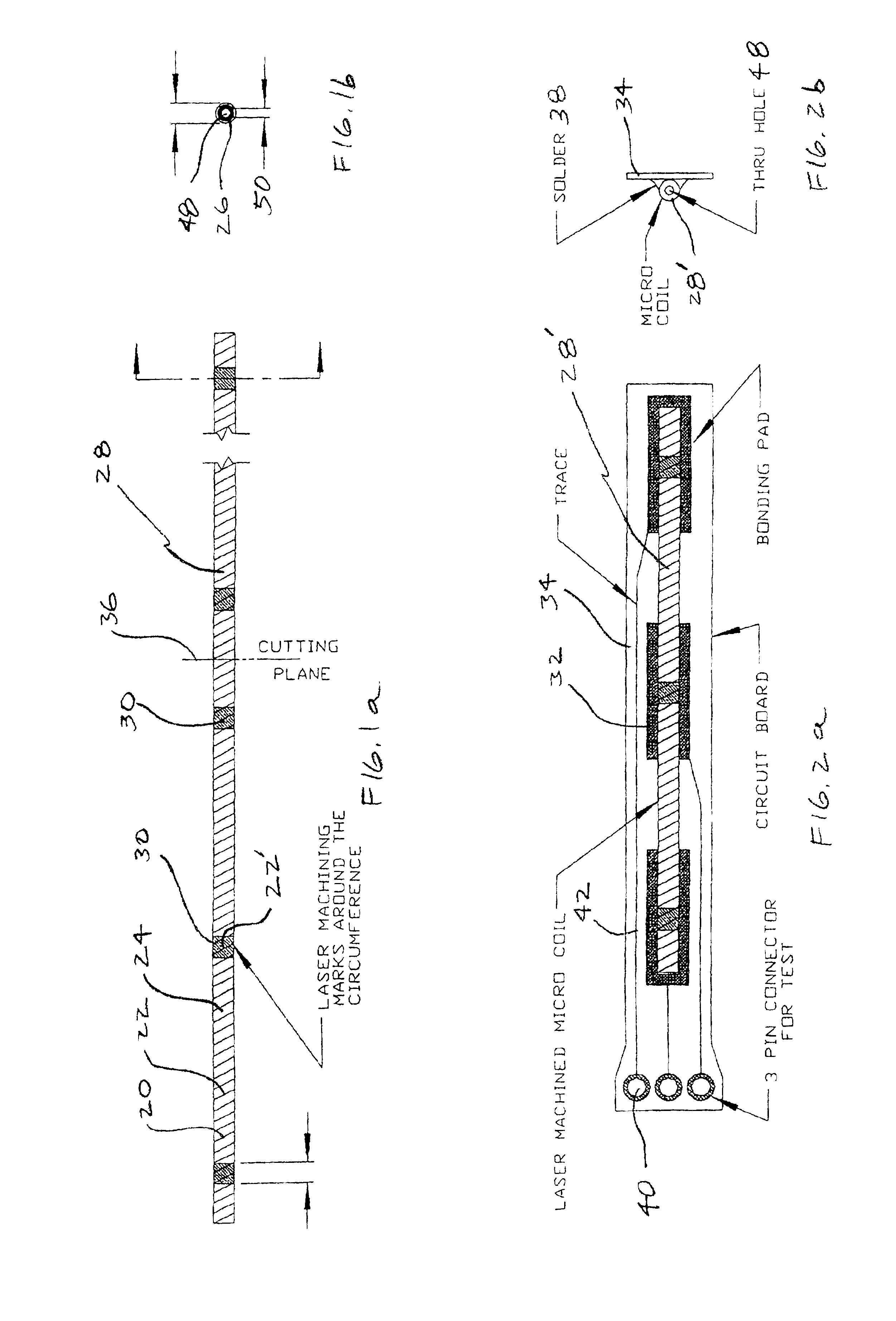
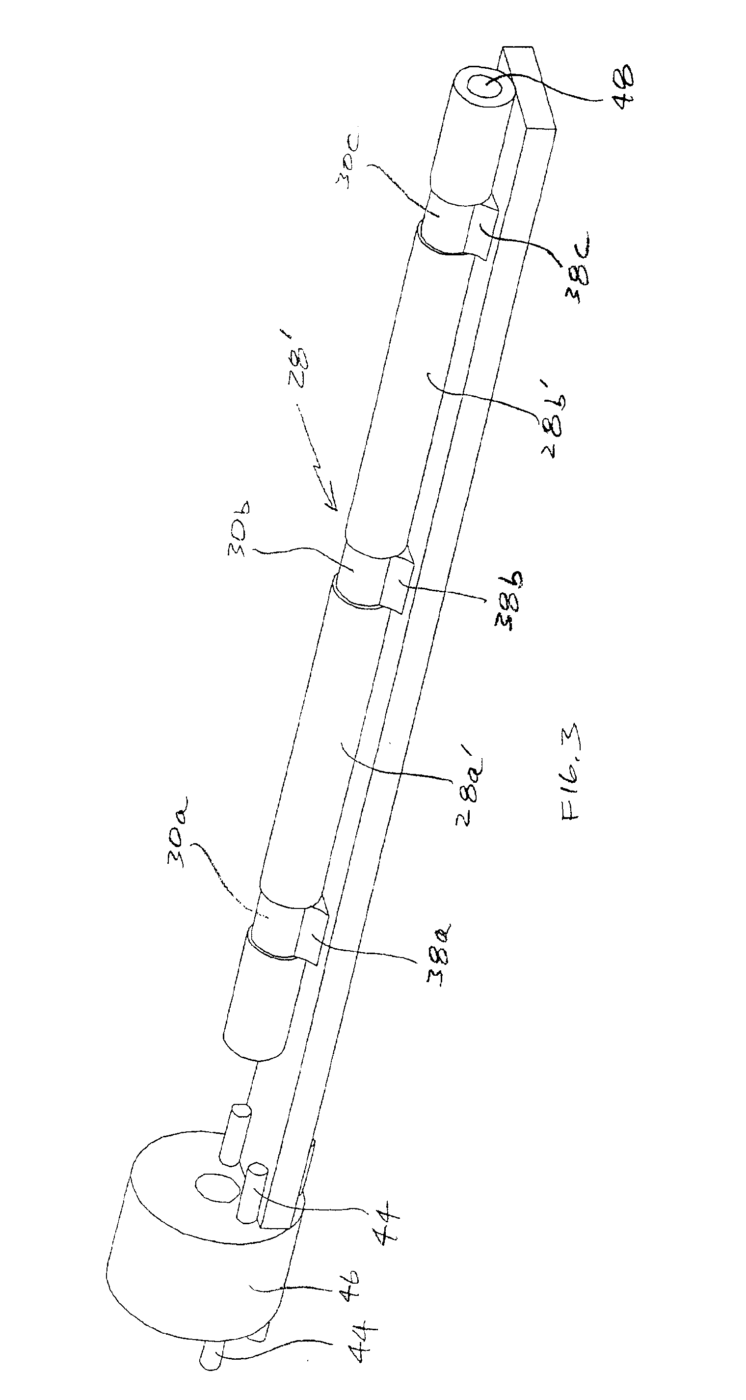
[0034]The present inventors recognized that a coil for their peak strain detector could be fabricated and handled more efficiently if contacts are formed on the surface of a coil that is wound on a hollow tube, avoiding the need to make contact to ends of delicate wires of the coil, while permitting use of a moveable core within the tube.

[0035]The present inventors also recognized that the surface mount approach allows a further lowering of the cost of fabricating coils for their peak strain detectors by integrating steps for many coils into a step for a single coil: A long coil is be wound. All the windows needed for contacts are opened, for example by laser ablation in the long coil. Then the long coil is diced into the short coils needed for an application, and each is surface mounted on a substrate using the windows in the insulation for the contacts. Thus winding of individual short coils is avoided, and handling reduced, providing higher reliability and lower cost.

[0036]The pr...


PUM

PropertyMeasurementUnit
Temperatureaaaaaaaaaa
Forceaaaaaaaaaa
Pressureaaaaaaaaaa

Abstract

Improved coils and clamps for variable reluctance sensors are disclosed. A method of fabricating a discrete coil involves providing a conductor wound in a coil on a tube. The coil has a coil outer surface that has insulation. A window is opened in the insulation on the coil outer surface to expose conductor of the coil for a contact. A movable core is provided within the tube for adjusting inductance of the coil. In one embodiment, the coil and tube are diced into small coils after the windows for each coil are opened. Another aspect the invention is a clamp comprising an elastic material, a shape memory alloy, and an apparatus for activating the shape memory alloy. The clamp holds the moveable core in its peak position. When the alloy is activated it changes shape and provides a force on the elastic material to change clamping state for resetting the transducer. The coils and clamps can be used for a variety of purposes in addition to the variable reluctance sensors.

Description

[0001]This application claims the benefit of Provisional application Ser. No. 60 / 174,903, filed Jan. 10, 2000.FIELD OF THE INVENTION[0002]This invention generally relates to sensors. More particularly, it relates to a microminiature, differential variable reluctance transducer capable of peak strain detection. Even more particularly, it relates to an improved coil, clamp, and package for such a peak strain detector, and an improved method of manufacturing a coil.BACKGROUND OF THE INVENTION[0003]Civil and military structures, such as buildings, dams, and bridges can benefit from smart sensors that can report the peak strain to which they have been exposed. Strain to such structures may peak when power is not available, such as during hurricanes, tornadoes, and earthquakes. Devices that do not need power that can measure and record the extent of strain that may have occurred at these times are especially important. Similarly, structures that are repeatedly stressed, such as helicopter...

Claims


Application Information

Patent Timeline
IPC IPC(8): G01B7/16G01B7/24H01F21/02H01F21/06H01F41/04
CPCG01B7/24H01F21/06H01F41/04Y10T29/49789Y10T29/49073Y10T29/49798Y10T29/49144Y10T29/49128Y10T29/4902Y10T29/4913
Inventor ARMS, STEVEN W.HAMEL, MICHAEL JMUNDELL, STEVEN WARDTOWNSEND, CHRISTOPHOR PRUYN
Owner LORD CORP
Why Eureka
Try Eureka