Liquid fertilizer distribution system and method

a technology of liquid fertilizer and distribution system, which is applied in the direction of water supply installation, combustion types, lighting and heating apparatus, etc., can solve problems such as variable distribution rate, and achieve the effects of improving fertilizer distribution rate, reducing rate variation between applicators, and improving distribution of substantially equal amounts of fertilizer

Inactive Publication Date: 2005-06-07
PARKER HANNIFIN CORP
View PDF6 Cites 5 Cited by
  • Summary
  • Abstract
  • Description
  • Claims
  • Application Information

AI Technical Summary

Benefits of technology

[0013]This invention has particular utility in applying fluid fertilizer, such as anhydrous ammonia (“NH3”), in an agricultural application. More particularly, this invention may improve distribution of a substantially equal amount of fertilizer to each of a plurality of applicator lines. The methods and apparatus of this invention provide a fertilizer distributor apparatus and system that improves fertilizer distribution rates and reduces rate variation between applicators. The improvement may be realized at least partially by distributing the fertilizer to each of the plurality of distributor lines substantially as a liquid phase, before creating or permitting fluid pressure-drops in the system. As discussed above, pressure drops may result in generation of a gas or vapor phase, which may result in variable distribution rates between applicator lines carrying a high percentage of gas phase and lines carrying a high percentage of liquid phase.

Problems solved by technology

As discussed above, pressure drops may result in generation of a gas or vapor phase, which may result in variable distribution rates between applicator lines carrying a high percentage of gas phase and lines carrying a high percentage of liquid phase.

Method used


Image

  • Liquid fertilizer distribution system and method
  • Liquid fertilizer distribution system and method
  • Liquid fertilizer distribution system and method

Examples


Embodiment Construction

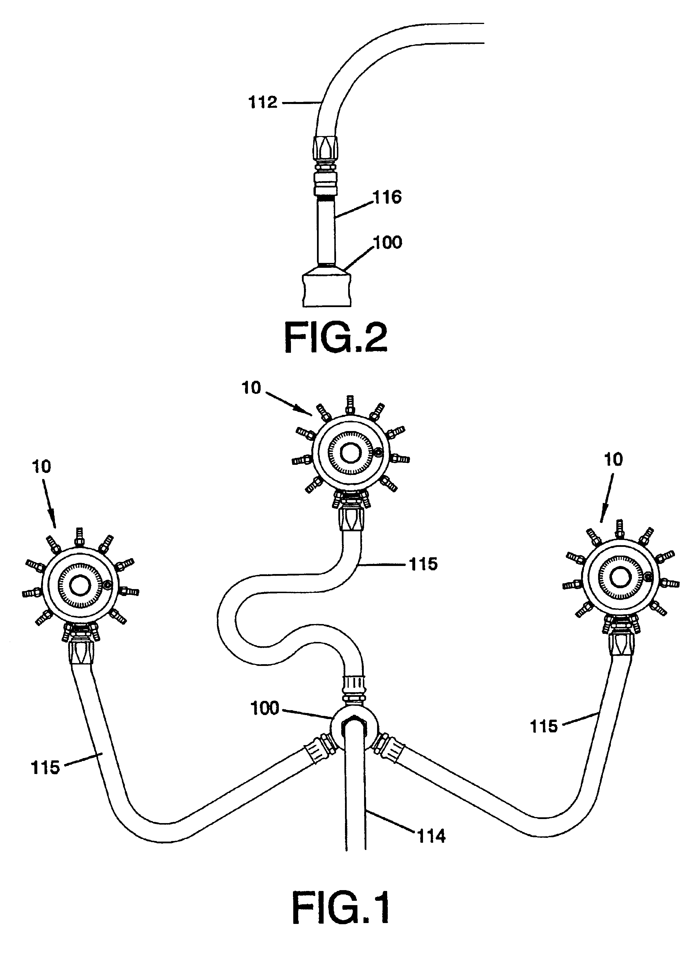
[0063]FIGS. 1 and 19 illustrate components that may be included in a fluid fertilizer distribution system according to the present invention, including a flow divider and three fluid distributors. A suitable system may include a tractor 92 pulling a knife implement 235 for breaking the soil, followed by a fluid fertilizer supply vessel 11. A primary supply hose 114 may conduct fertilizer from the supply vessel 11 to a flow divider 100, as shown in FIG. 1, or directly to a fluid distributor 10, as shown in FIG. 19.

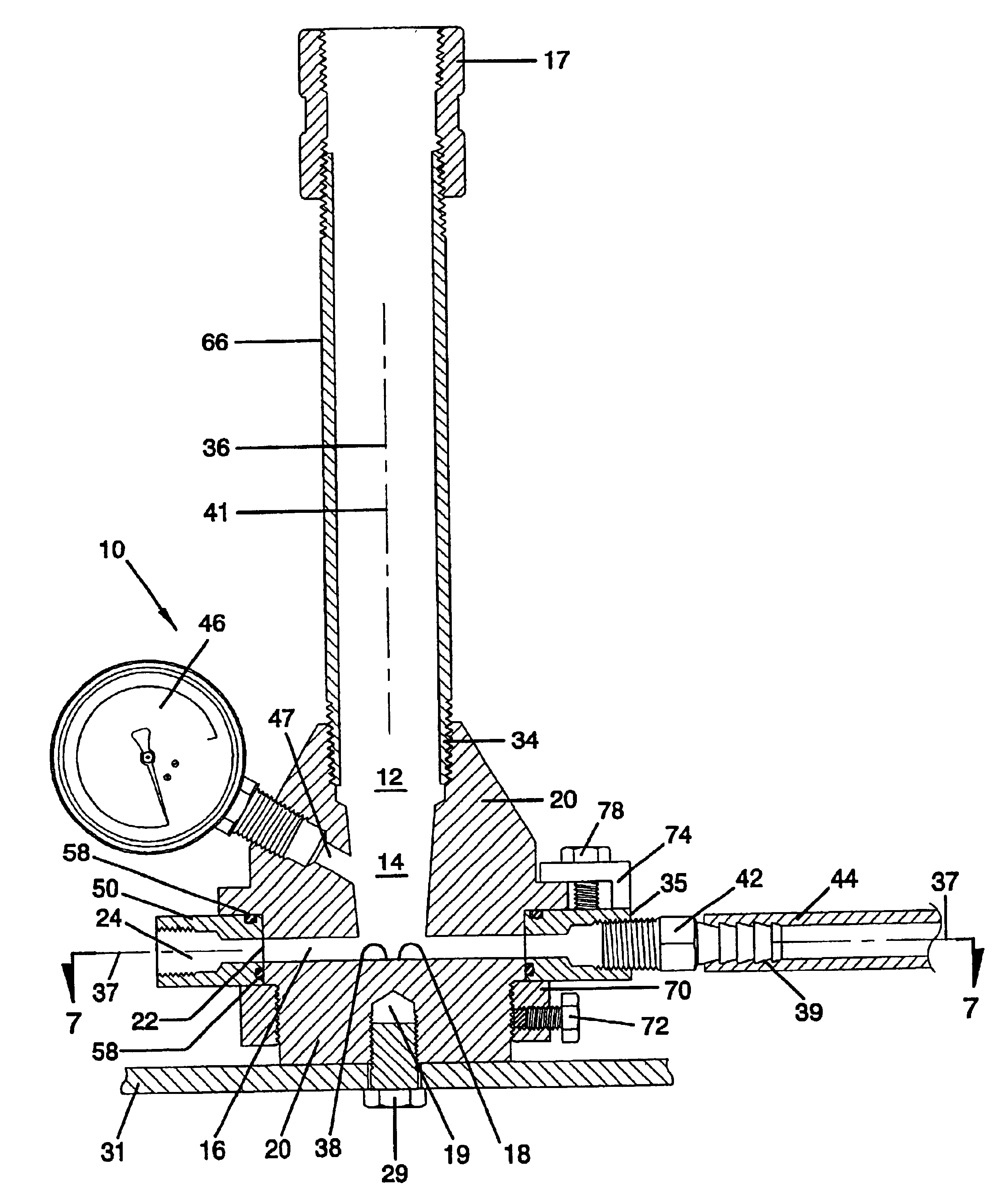
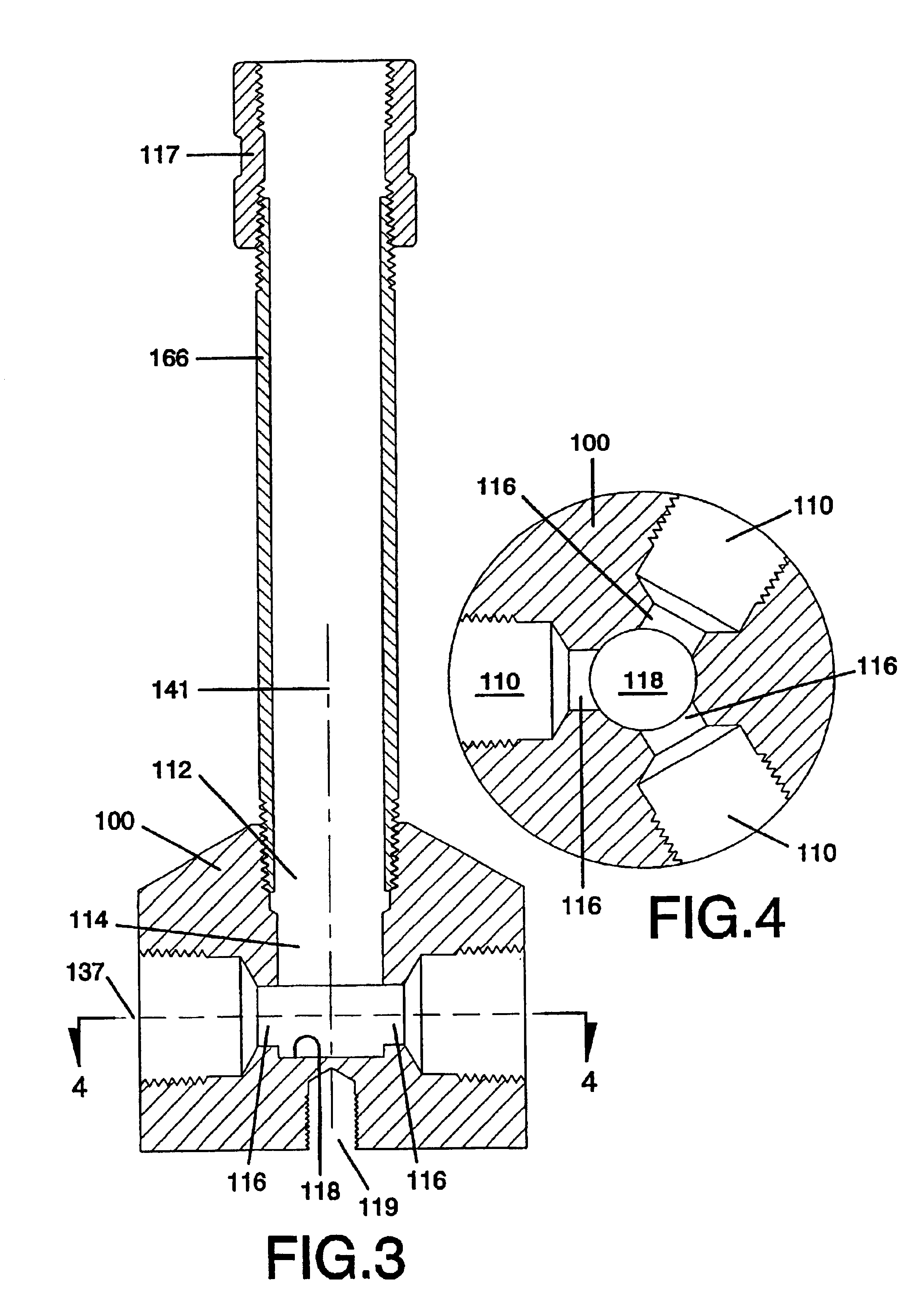
[0064]A flow divider 100, as illustrated in FIGS. 3 and 4, may be used to distribute fluid fertilizer from a primary supply hose 114 to at least two secondary supply hoses 14, each of which may conduct fluid fertilizer to a respective fluid distributor 10. Each fluid distributor 10 may distribute fertilizer to each of a plurality of applicator lines 44 and reduce the fluid pressure in the fertilizer during or after distribution. Each applicator line 44 may conduct the ferti...


PUM


Abstract

A removable flow restrictor 750 and a corresponding method for regulating flow through a fluid fertilizer distributor 700 are provided. A supply inlet port 712 is in fluid communication with a plurality of fluid outlet ports 716. The flow restrictor 750 is removable positionable within the fluid distributor 700 between the inlet port 712 and the outlet ports 716, for restricting flow between the inlet port 712 and the outlet ports 716. A restrictor engagement member 752, which may be a thread, on the flow restrictor 750, engages with a tool engagement member 762 on a retrieval tool 760. With the restrictor engagement member 752 engaged with the tool engagement member 762, the retrieval tool can be used to both position the flow restrictor 750 within the fluid distributor 700, and to remove the flow restrictor 750 from the fluid distributor 700. After positioning within or removing from the fluid distributor 700, the flow restrictor 750 may be disengaged from the retrieval tool 760.

Description

RELATED CASE[0001]The present application is a continuation-in-part of U.S. Ser. No. 09 / 778,518 filed Feb. 6, 2001, now U.S. Pat. No. 6,557,573.FIELD OF THE INVENTION[0002]The present invention relates to applying fluids to crop fields in the agricultural industry using a multiple distribution point applicator. More particularly, this invention relates to uniformly distributing and selectively outputting multiple fluid streams of a single or multiple-phase fluid from a fluid distributor manifold. More particularly, this invention relates to an improved method and system for distributing liquid fertilizer at a substantially equal rate to each of a plurality of distribution lines. The method and system of this invention facilitate more even distribution of fertilizer to each of the plurality of knives on an applicator.BACKGROUND OF THE INVENTION[0003]Agricultural crop producers routinely apply liquid fertilizer to crop fields to replenish depleted nutrients beneficial to crop producti...

Claims


Application Information

Patent Timeline
Patent Type & Authority Patents(United States)
IPC IPC(8): A01C23/04A01C23/00A01C23/02B05B9/03B05B1/14F16K3/22F16K3/00F16K11/07F16K11/065F16K11/076F16K11/06
CPCA01C23/007A01C23/024A01C23/04F16K11/076B05B9/03F16K3/22F16K11/07B05B1/14Y10T137/0318Y10T137/0491Y10T137/6109Y10T137/6154Y10T137/8275Y10T137/85938Y10T137/86686Y10T137/86863Y10T137/87153Y02P60/21
Inventor NIMBERGER, SPENCER M.
Owner PARKER HANNIFIN CORP
Why Eureka
Try Eureka