Coaxial electrical connector

a technology of electrical connectors and coaxial cables, applied in the direction of coupling device details, coupling device connections, two-pole connections, etc., can solve the problem of more gaps, achieve the effect of eliminating the adhesion of molten solder and preventing the separation of the central conductor from the dielectric block

Inactive Publication Date: 2005-06-07
HIROSE ELECTRIC GROUP
View PDF6 Cites 37 Cited by
  • Summary
  • Abstract
  • Description
  • Claims
  • Application Information

AI Technical Summary

Benefits of technology

[0011]Accordingly, it is an object of the invention to provide a low-profile coaxial electrical connector that is able to prevent the molten solder from reaching the central conductor and permit the dielectric block to hold the central conductor sufficiently firmly to prevent displacement.
[0014]Since the central conductor is meshed with the dielectric block at the raised and / or indented portion, the gripping power of the central conductor by the dielectric block is improved. Consequently, the central conductor is hardly separated by external forces, and the soldering heat makes little gap between the dielectric block and the central conductor to prevent advancement of the molten solder into the gap.
[0015]It is preferred that the surface-processed portion is an indented portion formed on the bottom edge of the radial section and filled with part of the dielectric block. Consequently, the central conductor is embraced by the dielectric block with the improved retention power. Not only the width of the edge is so small that little influence is made on the area of the connection portion but also the length of the edge is so large that the strength is improved. The width of the edge that is filled with the dielectric block may be increased on the area that is not used as the connection portion.
[0016]The indented portion may be formed as a through-hole. The dielectric block fills the through-hole and holds the central conductor between the upper and lower portions, thereby improving the retention power.
[0025]As described above, according to the invention, there is provided the surface-processed portion on the face of the central conductor that is in contact with the dielectric block so as to form at least one of the raised portion and the indented portion so that the retention and engaging forces of the central conductor by the dielectric block are improved but also the separation of the central conductor from the dielectric block is prevented, which eliminates adherence of the molten solder to the central conductor.

Problems solved by technology

Since the connector must be low in profile, the bottom wall of the dielectric block is made so thin that it is prone to displacement by external forces or thermal expansion, making more gaps.

Method used


Image

  • Coaxial electrical connector
  • Coaxial electrical connector
  • Coaxial electrical connector

Examples


first embodiment

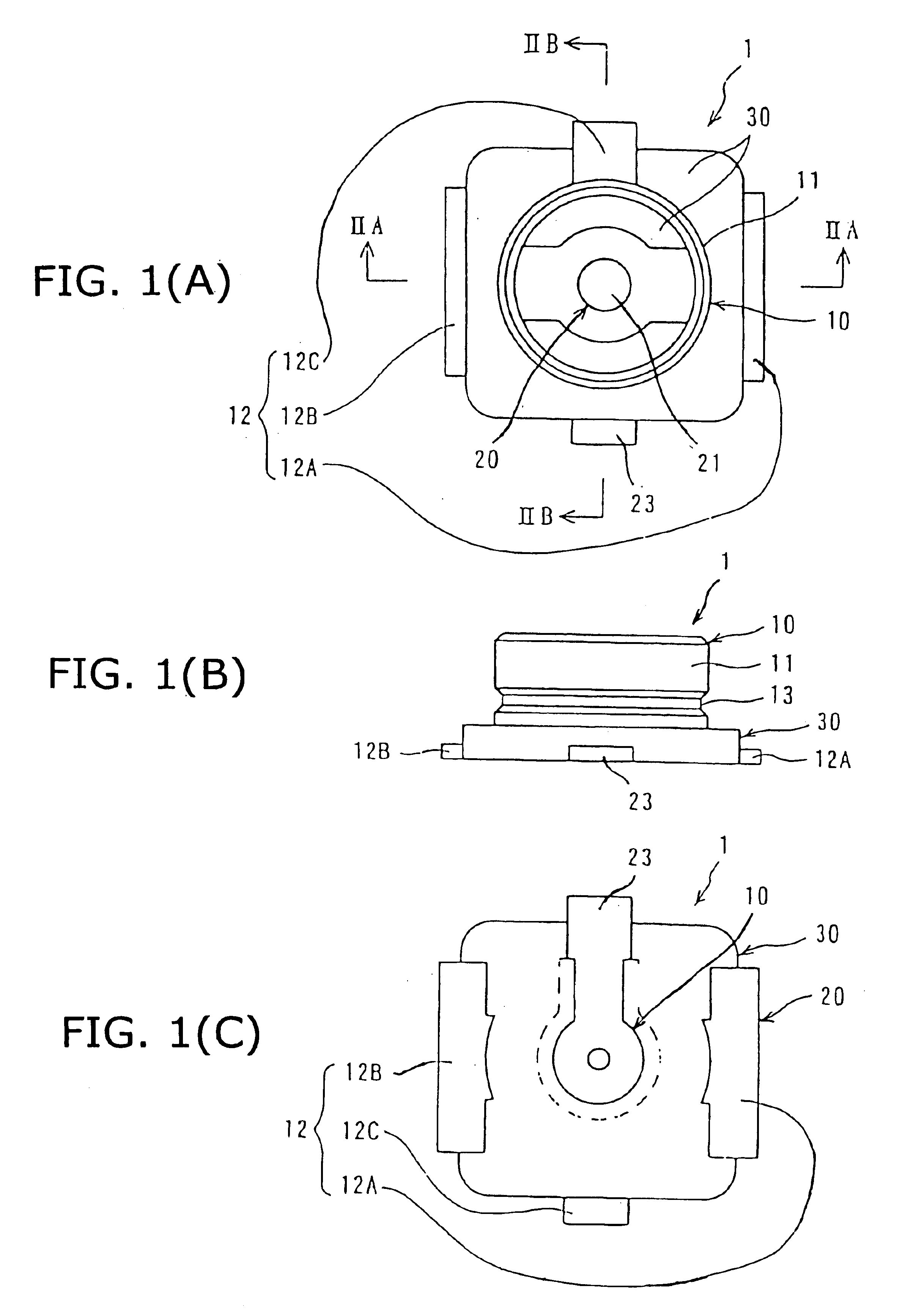
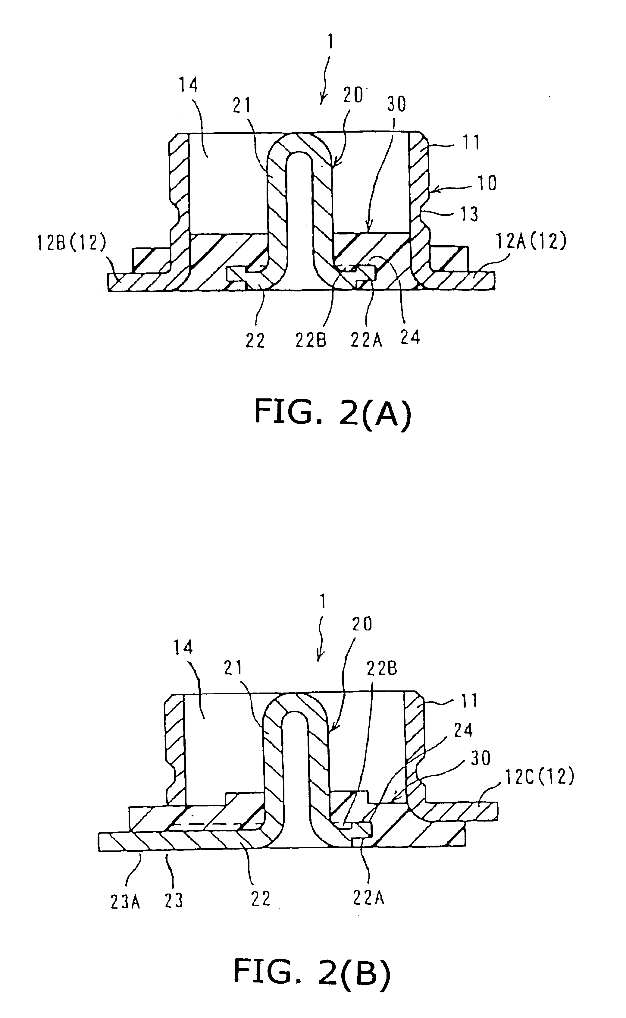
[0043]In FIGS. 1 and 2, a coaxial connector 1 according to the first embodiment comprises a dielectric block 30 that integrally holds an outer conductor 10 and a central conductor 20 as a unit.

[0044]The outer conductor 10 is made by bending and forming a metal sheet so as to provide a tubular section 11 having an axial line in the plugging direction with a mating connector and three leg sections 12 extending outwardly from the bottom of the tubular section 11. The tubular section 11 is provided with an engaging groove 13 for engagement with the outer conductor of a mating connector (not shown) for preventing separation. A pair of leg sections 12A and 12B, which are diametrically opposed to each other, are made relatively wide and the other leg section 12C is narrower than these two leg sections. The leg sections 12A and 12B are flush with the bottom face of the connector 1 so that when the connector is placed on a circuit board, they are brought into contact with the circuit traces....

second embodiment

[0054]The second embodiment will be described with reference to FIG. 7. A ridge portion 23B extends in a widthwise direction of the extension portion 23 It is made by embossing a groove portion 23C under the ridge portion 23B. It is preferred that it extends across the entire or almost entire width of the extension portion 23. It not only increases the engaging power between the extension portion 23 and the dielectric block 30 but also prevents the molten solder from advancing beyond the ridge portion 23B even if there is a small gap between the extension portion23 and the dielectric block 390. In order to provide this labyrinth effect, a recessed portion may be added to the ridge portion or to replace it. It may be replaced by a plurality of corrugations without the groove portion 23C. It not only has the labyrinth function but also increases the engaging power with the dielectric block 30. It is not necessary to be a narrow ridge but may be a wide ridge.

third embodiment

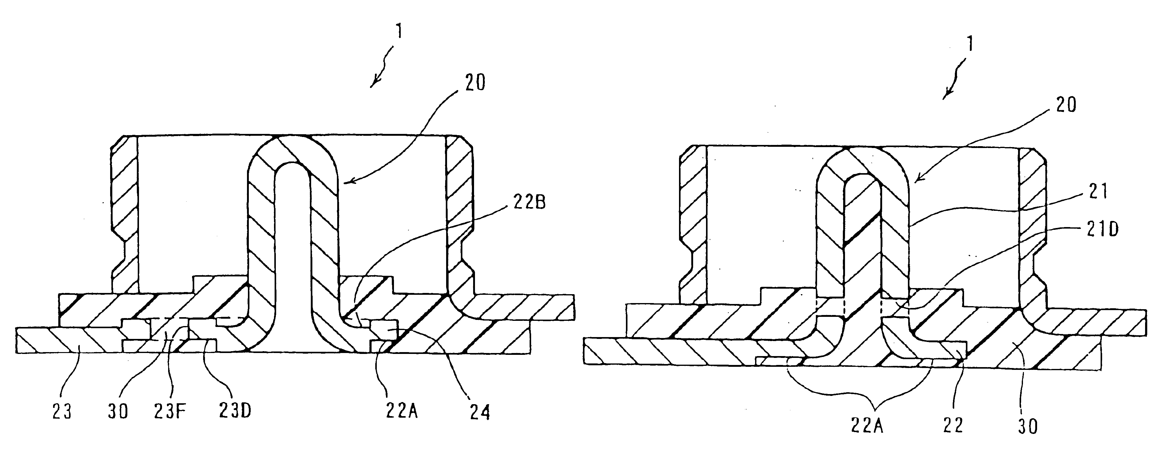
[0055]The third embodiment will be described with reference to FIGS. 8 and 9. Similarly to the first embodiment, there are provided on the edge of the radial Section 22 the indented portion 22A and the indented portion 22B that is defined by the raised portion 24 and filled with the dielectric block 30.

[0056]In FIG. 8, a wide indented portion 23D is provided in the extension portion 23 and filled with the dielectric block 31. The formation of the indented portion 23D provides a raised portion 23E. These wide indented and raised portions 23D and 23E increase the engaging power by the dielectric block 30. The raised portion 23E also improves the function of preventing advance of the molten solder.

[0057]In FIG. 9, a through-hole 23F is provided in the extension portion 23 on the indented portion 23D so that the dielectric block 30 is connected through the through-hole 23F, This permits the dielectric block 30 holds the extension portion 23 between the upper and lower portions, improvin...


PUM


Abstract

A coaxial electrical connector comprises an outer conductor (10) having a tubular section (11); a central conductor (20) having a contact section (21) extending in the axial direction in the tubular section (11); and a dielectric block (30) molded to hold together both the conductors (10, 20). The central conductor (20) has a radial section (22) extending outwardly in the radial direction from the bottom of the contact section (21) and a connection portion (23A) on the bottom face of the radial section (22) for contact with a circuit board. The central conductor 20 has a surface-processed portion so as to form at least one of a raised portion (24) and an indented portion (22A) and is in contact with the dielectric block at the surface-processed portion.

Description

BACKGROUND OF THE INVENTION[0001]1. Field of the Invention[0002]The present invention relates to coaxial electrical connectors.[0003]2. Description of the Related Art[0004]Japanese Patent Application Kokai No. 8-321361 discloses a coaxial connector receptacle of this type.[0005]As shown in FIGS. 16(A) and (B), this connector comprises a rectangular dielectric block 51 having a recessed section, a tubular outer conductor 52 having a substantially S-shaped cross-section in a plane including an axial line and provided on the recessed section, and a central conductor 53 having a contact section 54 that extends upwardly into the recessed section.[0006]The central conductor 53 has a connection section 55 together with the contact section 54. The connection section 55 extends in a radial direction (FIG. 16(B)) and is flush with the bottom face of the dielectric block 51 so that when the connector is placed on the circuit trace of a circuit board, it is brought into contact with the trace a...

Claims


Application Information

Patent Timeline
Patent Type & Authority Patents(United States)
IPC IPC(8): H01R13/00H01R13/646H01R4/02H01R43/02
CPCH01R24/50H01R4/023Y10S439/944H01R43/0256H01R2103/00H01R43/0235
Inventor YAMANE, MASAHIRO
Owner HIROSE ELECTRIC GROUP
Why Eureka
Try Eureka