Contact unit and socket for electrical parts

Active Publication Date: 2005-06-07
ENPLAS CORP
View PDF5 Cites 34 Cited by
  • Summary
  • Abstract
  • Description
  • Claims
  • Application Information

AI Technical Summary

Benefits of technology

[0014]In such a construction, the contact which is housed in the hole portion provided in at least one face of the insulating member and is urged outwards by the resilient member to protrude from the hole portion, is pressed by the connection terminal of the electrical part detachably mounted on the mounting portion to bend the resilient member, and is brought into contact with the conductive member, which is provided on the internal circumference surface of the hole portion to electrically connect between the contact and the circuit board, thus enabling to electrically connect the electrical part and the cir

Problems solved by technology

In particular, this variation in the connection resistance and inductance is caused by unstable electrical connection, so

Method used


Image

  • Contact unit and socket for electrical parts
  • Contact unit and socket for electrical parts
  • Contact unit and socket for electrical parts

Examples


first embodiment

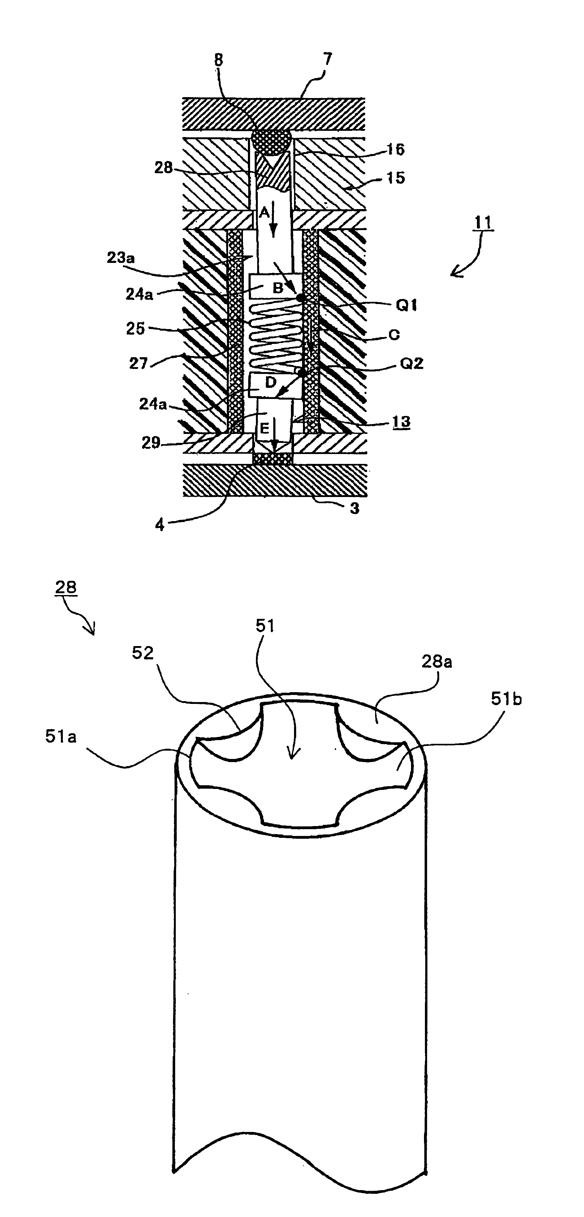
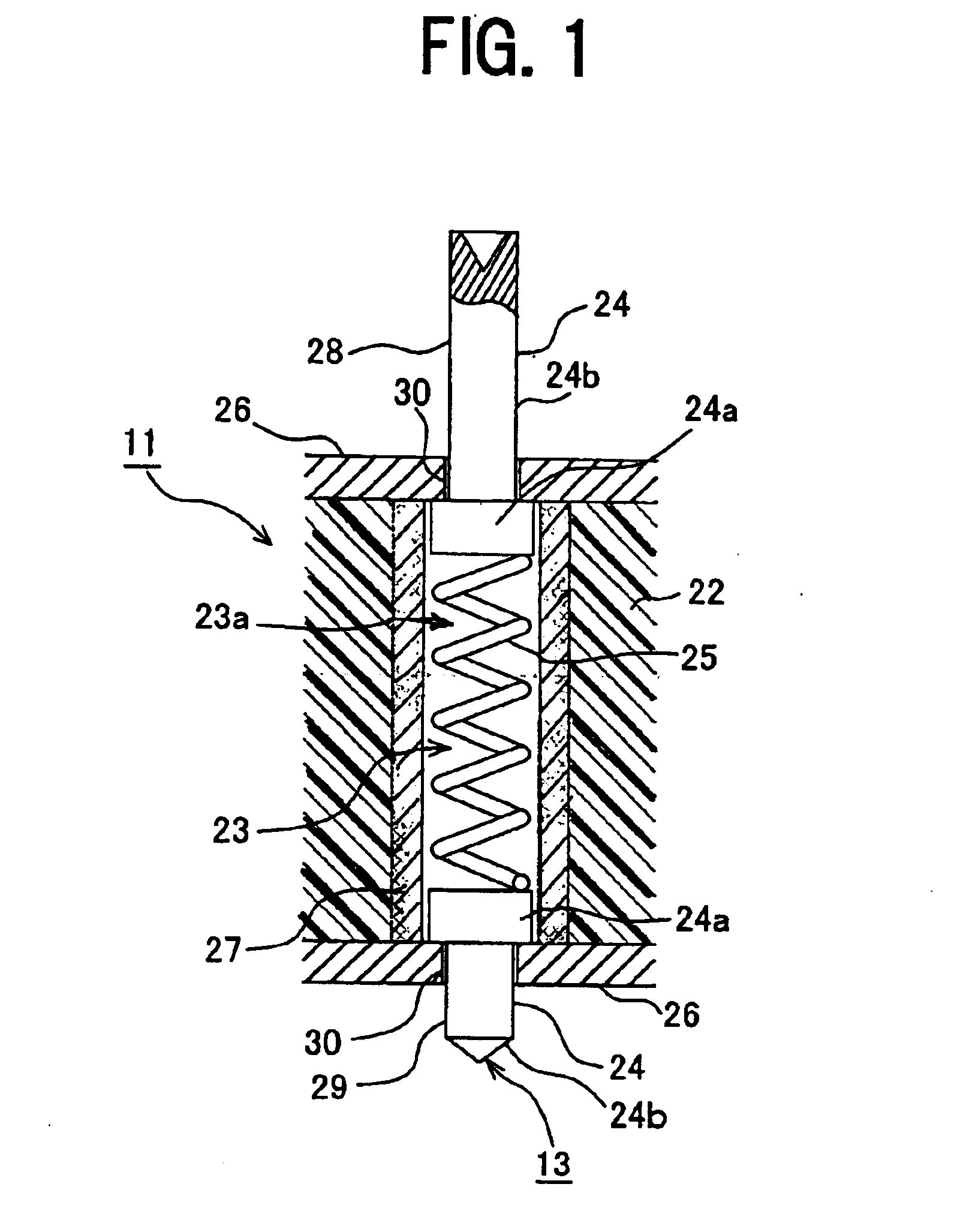
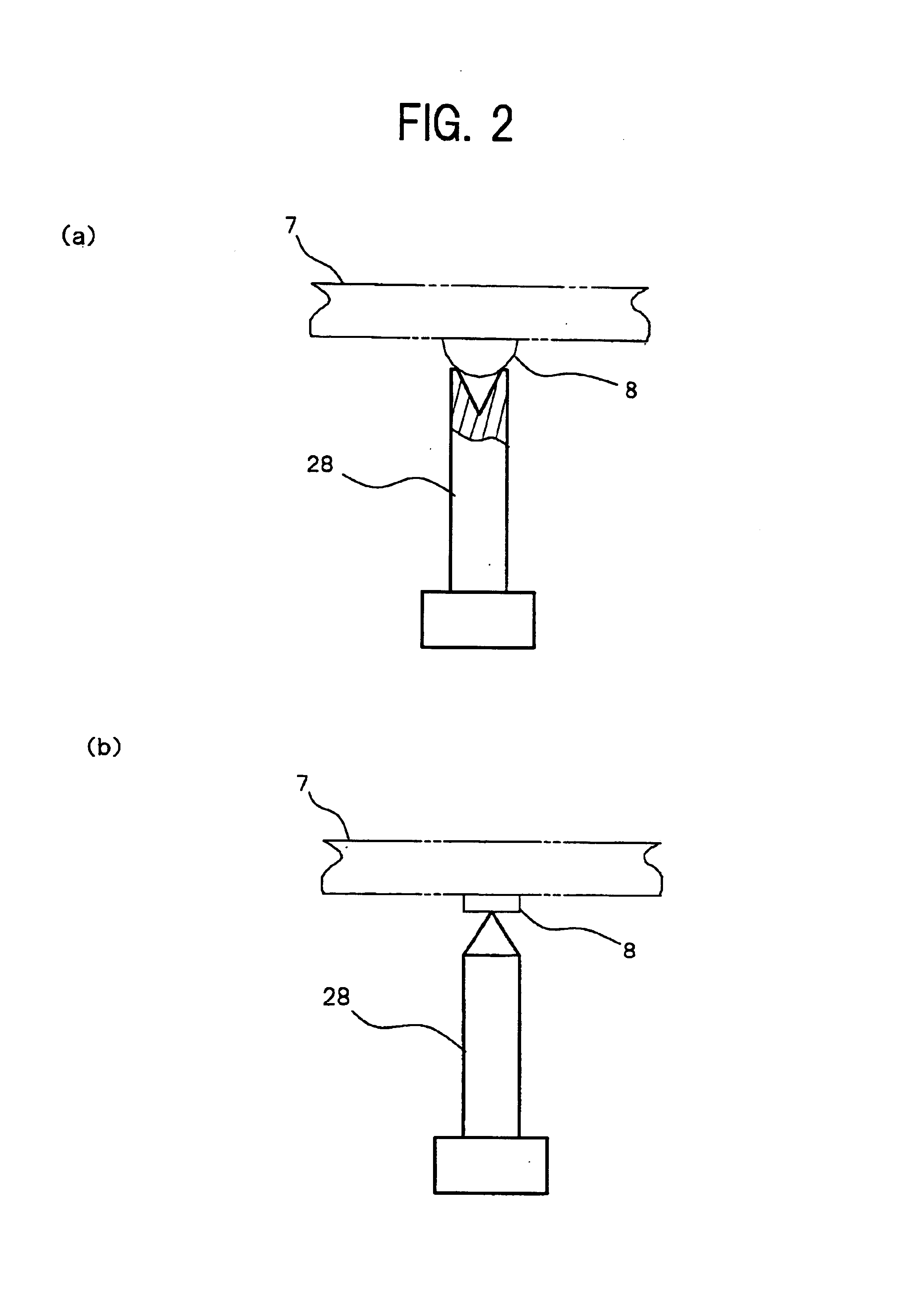
[0031]FIG. 1 is a cross-sectional view describing a contact unit according to the present invention. This contact unit 11 electrically connects two connection objects, and comprises an insulating member 22 and a connecting device 13. Hereunder, a description will be made for the case where an electrical part and a circuit board are adopted as the two connection objects.

[0032]The insulating member 22 is made of glass, ceramic or the like, for example, and is formed with a hole portion 23 in at least one face thereof. The hole portion 23 houses and retains therein the connecting device 13, and its internal circumference surface is made smooth by grinding or the like. To be specific, the hole portion 23 includes a through hole 23a which is formed to pass through the insulating member 22. A plurality of hole portions 23 is formed corresponding to a plurality of connection terminals of the electrical part and a plurality of contact electrodes of the circuit board. Note, the insulating me...

second embodiment

[0068]Next is a description of the contact unit 11 according to the present invention with reference to FIG. 10.

[0069]In this contact unit 11, the insulating member 22 is a multi-layer wiring board, and wiring paths 35a to 35e disposed on the respective layers are connected appropriately to respective conductive members 27a to 27e of through holes 23a. To describe a specific example, a plurality of through holes 23a is provided on the multi-layer wiring board corresponding to the connection terminals 8 of the electrical part 7, and the connecting device 13 is housed in each through hole 23a. The wiring paths 35a and 35b on the first layer of the multi-layer wiring board are respectively connected to the conductive members 27a and 27b of the through holes 23a, the wiring path 35c on the second layer to the conductive member 27c, and the wiring paths 35d and 35 on the third layer are respectively connected to the conductive members 27d and 27e, The other ends of the wiring paths 35a t...


PUM


Abstract

There are provided a pair of contacts which are housed in a hole portion formed in an insulation member, to be brought into contact with two connection objects, a conductive member provided on an internal circumference surface of the hole portion, and a resilient member which urges the contacts outwards and is deformed due to the urging of the contacts to electrically connect the contacts to the conductive member, wherein the connection objects are pressed to be in contact with the two contacts, thus bending the resilient member, so that the contacts are brought into contact with the conductive member at fixed positions to thereby ensure a stable electrical connection between the two connection objects.

Description

BACKGROUND OF THE INVENTION[0001]1. Field of the Invention[0002]The present invention relates to a contact unit and a socket for electrical parts, for electrically connecting two connection objects. In particular, the present invention relates to a contact unit and a socket for electrical parts, for pressing connection objects to be in contact with contacts, which are housed in a hole portion disposed with a conductive member on an internal circumference surface thereof and protrude by being urged outwards by a resilient member, to bend the resilient member, and bringing the contacts into contact with the conductive member at fixed positions, to ensure a stable electrical connection.[0003]2. Description of the Related Art[0004]Heretofore, such a type of contact unit has been disclosed in Japanese Unexamined Patent Publication No. 11-297439, which is applied to a socket for electrical parts used for performance testing of electrical parts. In this contact unit, the main parts of whic...

Claims


Application Information

Patent Timeline
IPC IPC(8): H01R13/24H01R13/22H01R11/18
CPCG01R1/045H01R12/714H01R13/2421G01R1/06722G01R1/0483
Inventor WATANABE, TSUYOSHI
Owner ENPLAS CORP
Why Eureka
Try Eureka