Composite bone graft, method of making and using same

a bone graft and composite technology, applied in the field of bone grafts, can solve the problems of insufficient load bearing, insufficient wideness of cortical bone obtained from cadaver sources fashioned into struts, and failure of bone grafts for spinal applications, so as to avoid significant donor site morbidity and adequate mechanical strength

Inactive Publication Date: 2005-06-07
LIFENET HEALTH
View PDF30 Cites 171 Cited by
  • Summary
  • Abstract
  • Description
  • Claims
  • Application Information

AI Technical Summary

Benefits of technology

[0007]The present invention is directed to a composite bone graft for repairing bone defects caused by congenital anomaly, disease, or trauma, including for example, for restoring vertical support of the posterior and/or anterior column. The present composite bone grafts can be used as structural grafts placed posteriorly in the spine as interbody grafts or as strut grafts spanning multiple segments. Poster

Problems solved by technology

For example, cortical bone obtained from a cadaver source fashioned into struts, is not wide enough for optimum load bearing.
This natural limitation often excludes the use of a bone graft product.

Method used


Image

  • Composite bone graft, method of making and using same
  • Composite bone graft, method of making and using same
  • Composite bone graft, method of making and using same

Examples


examples

I. Preparation of a Composite Graft

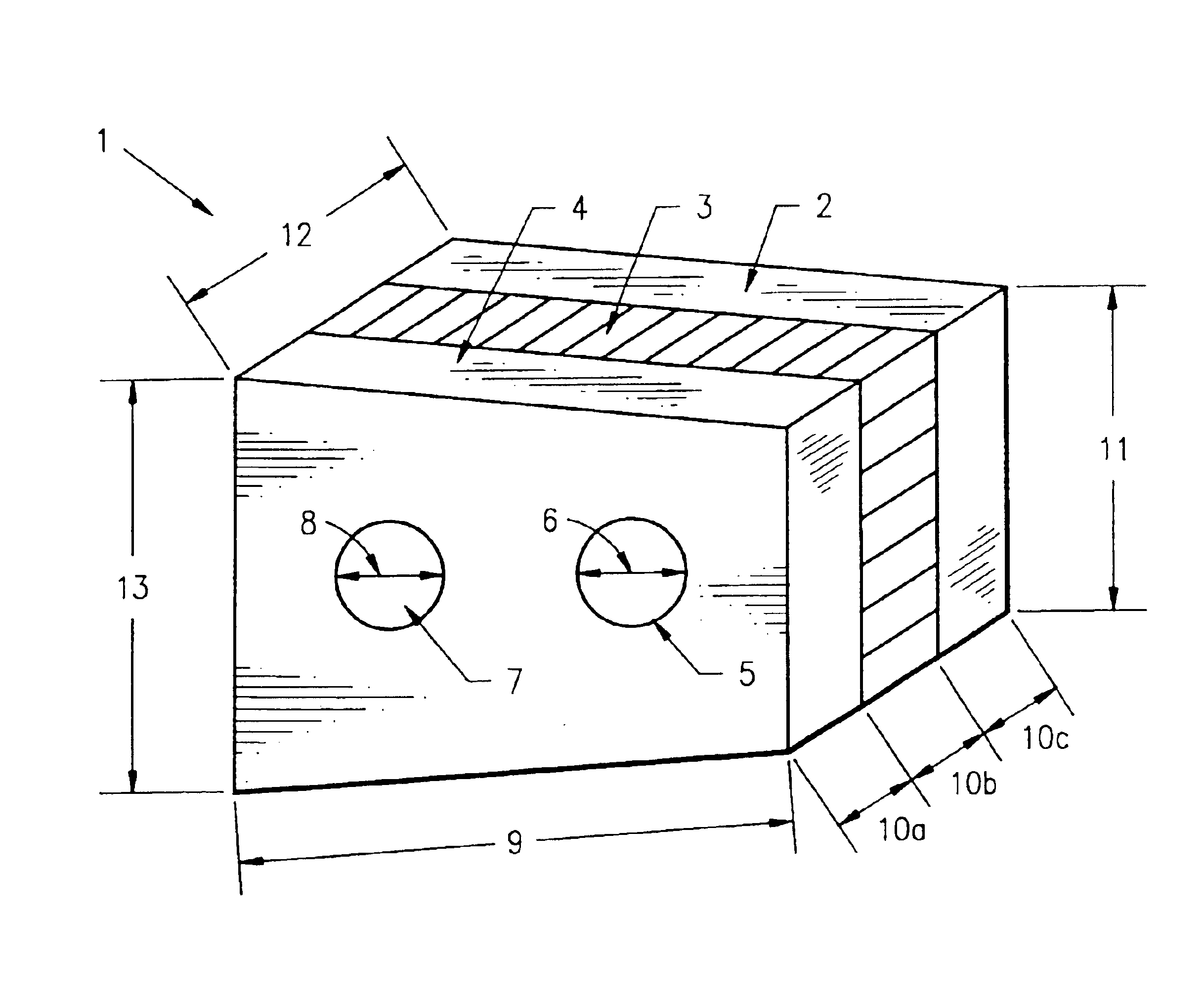
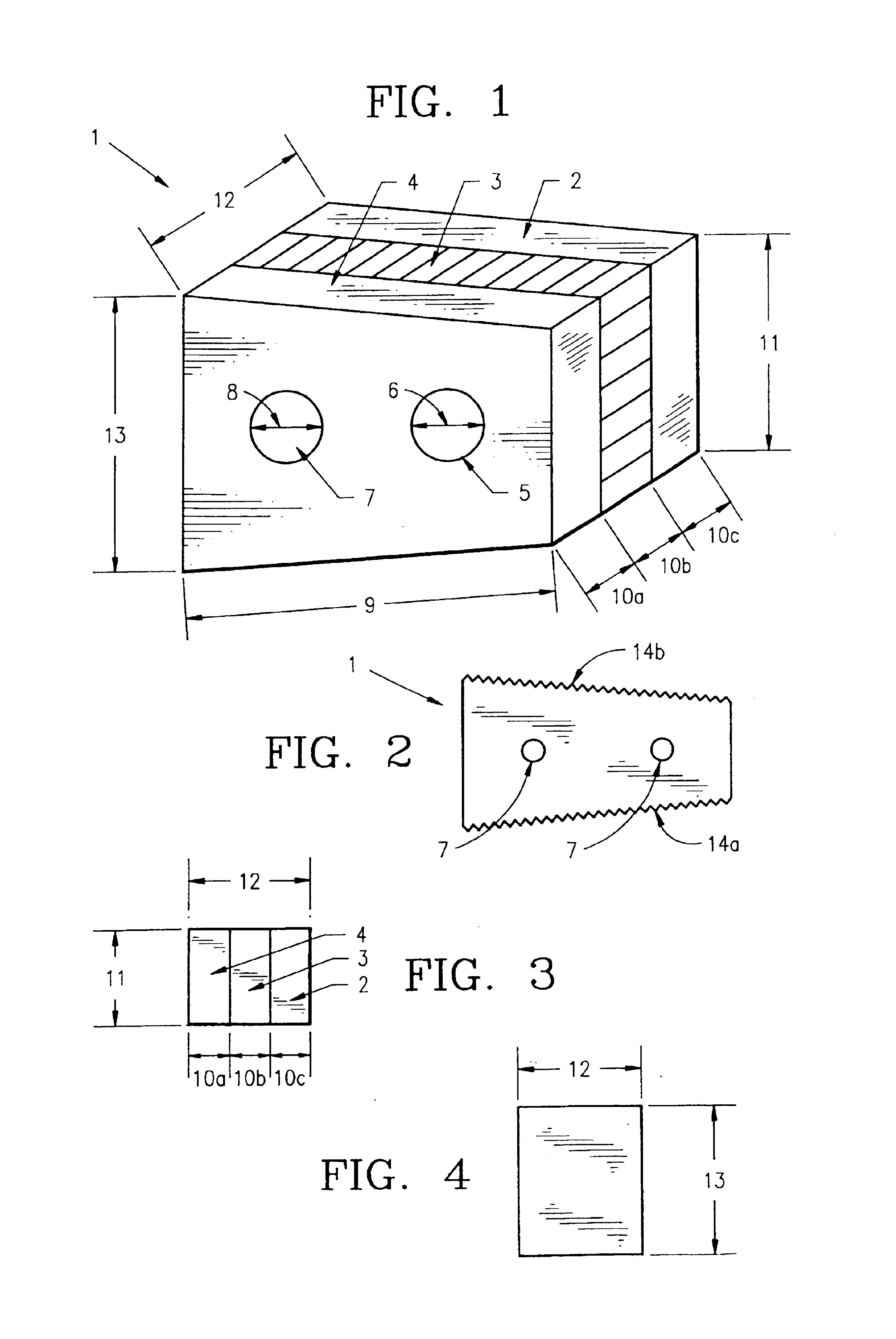
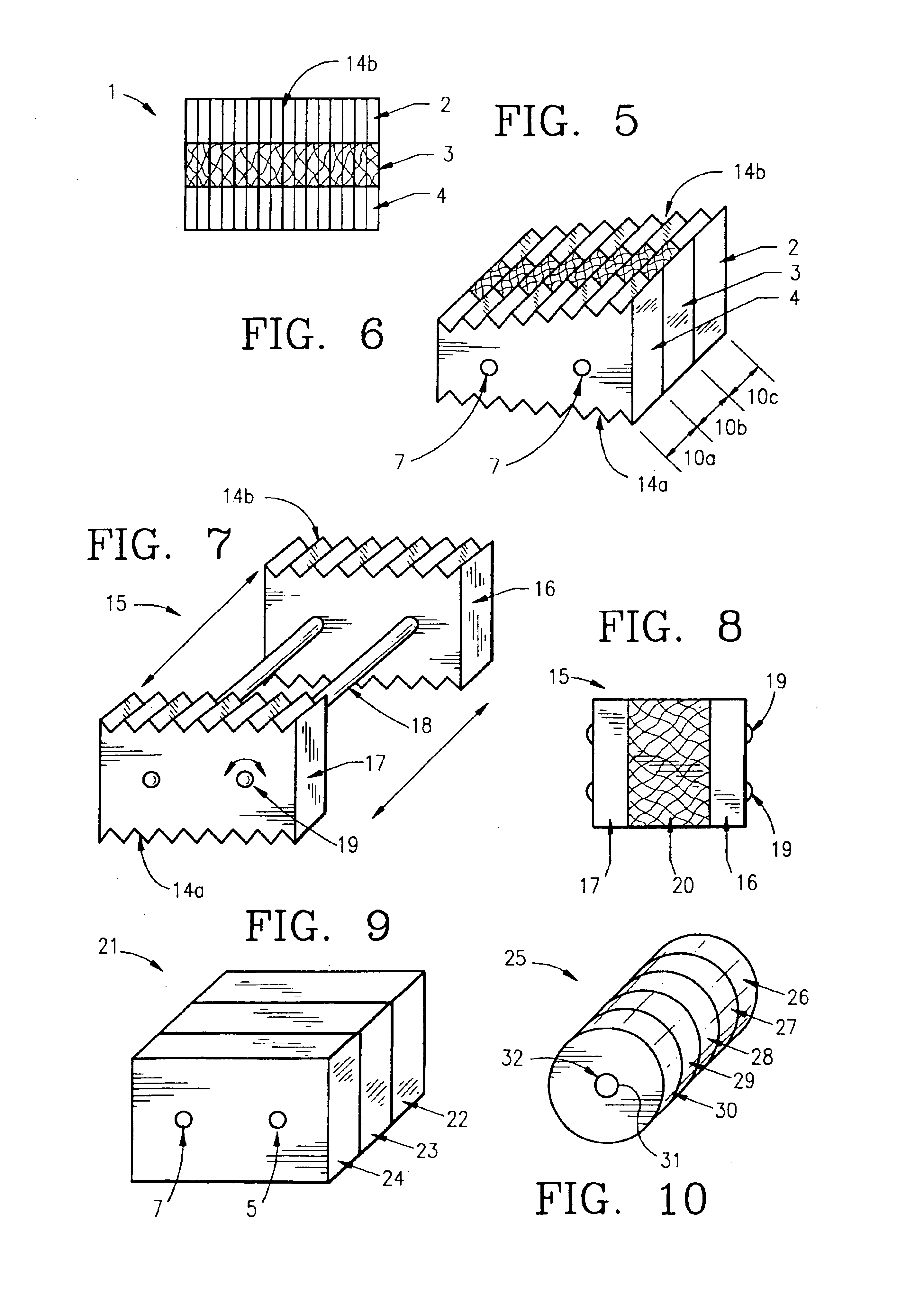
[0268]Donor bone was harvested according to industry accepted standards from a cadaver donor. The composite bone grafts, sized as recorded in Table 1, were prepared according to the method described as follows. Using a bandsaw cortical planks and pin segments were cut from a cortical shaft. One surface of each cortical planks was smoothed on a planing table and the planks were cut to the recorded thickness using a mill. Thereafter, using a table saw, the cut planks were cut to the recorded width and length. Cortical pins were then cut using a drill press, from the pin segments. Using a drill sander, the cortical pins were tapered sufficient to allow insertion into the reamed graft unit. Next, using a bandsaw, cancellous wafers were cut from cancellous bone to the recorded thickness. The wafers were then cut to the recorded width and length using a table saw. The cortical planks and cancellous wafer were then assembled into a graft unit in a jig and...


PUM

PropertyMeasurementUnit
Lengthaaaaaaaaaa
Lengthaaaaaaaaaa
Lengthaaaaaaaaaa

Abstract

The invention is directed to a composite bone graft for implantation in a patient, and methods of making and using the composite bone graft, along with methods for treating patients by implanting the composite bone graft at a site in a patient. The composite bone graft includes two or more connected, discrete, bone portions, and includes one or more biocompatible connectors which hold together the discrete bone portions to form the composite bone graft. The composite bone graft may include one or more textured bone surfaces. The textured surface preferably includes a plurality of closely spaced protrusions, preferably closely spaced continuous protrusions. The composite bone graft is useful for repairing bone defects caused by congenital anomaly, disease, or trauma, in a patient, for example, for restoring vertical support of the anterior and/or posterior column. Implantation of the composite bone graft results in improved graft stability and osteoinductivity, without a decrease in mechanical strength. The composite bone graft does not shift, extrude or rotate, after implantation. The present composite bone graft can be appropriately sized for any application and can be used to replace traditional non-bone prosthetic implants.

Description

[0001]This application is a Continuation-in-Part application of U.S. patent application Ser. No.: 09 / 286,975, filed Apr. 6, 1999 now abandoned, which is a Continuation-in-Part of U.S. patent application Ser. No.: 09 / 225,299, now abandoned filed Jan. 5, 1999, now abandoned, which is a Continuation-in-Part of application Ser. No. 09 / 368,263, filed Aug. 3, 1999, now U.S. Pat. No. 6,200,347.FIELD OF THE INVENTION[0002]The invention relates to bone grafts and more particularly, to bone grafts useful for spinal fusion. The invention provides a composite bone graft for implantation in a patient, and methods of making and using the composite bone graft. The composite bone graft contains two or more distinct bone portions where the bone portions are connected. The bone portions are preferably self-locking, interlocking, and / or connected by at least one mechanical connector, including for example, a bone pin. One or more of the bone portions may be demineralized, and may also be continuous or...

Claims


Application Information

Patent Timeline
IPC IPC(8): A61F2/28A61F2/44A61L27/40A61L27/00A61L27/36A61F2/00A61F2/30A61F2/02A61L27/44A61L27/46A61L27/48
CPCA61F2/28A61F2/4455A61F2/447A61L27/3608A61L27/365A61L27/40A61L27/446A61L27/46A61L27/48A61L27/54A61L27/36A61L27/14A61L27/02A61F2/3094A61F2/442A61F2002/2817A61F2002/2835A61F2002/2839A61F2002/30004A61F2002/30057A61F2002/30062A61F2002/30113A61F2002/30125A61F2002/30131A61F2002/30143A61F2002/30153A61F2002/30154A61F2002/30156A61F2002/30158A61F2002/30224A61F2002/30261A61F2002/30263A61F2002/3028A61F2002/30329A61F2002/30383A61F2002/30387A61F2002/30492A61F2002/30494A61F2002/30599A61F2002/30604A61F2002/30677A61F2002/30777A61F2002/30785A61F2002/30904A61F2002/30971A61F2210/0004A61F2220/0025A61F2230/0006A61F2230/0008A61F2230/0013A61F2230/0017A61F2230/0019A61F2230/0021A61F2230/0023A61F2230/0026A61F2230/0063A61F2230/0069A61F2230/0082A61F2230/0084A61F2240/001A61F2250/0014A61F2250/0063A61F2310/00017A61F2310/00023A61F2310/00029A61F2310/00179A61F2310/00329A61L2430/02
Inventor ANDERSON, BILLY G.WOLFINBARGER, JR., LLOYD
Owner LIFENET HEALTH
Why Eureka
Try Eureka