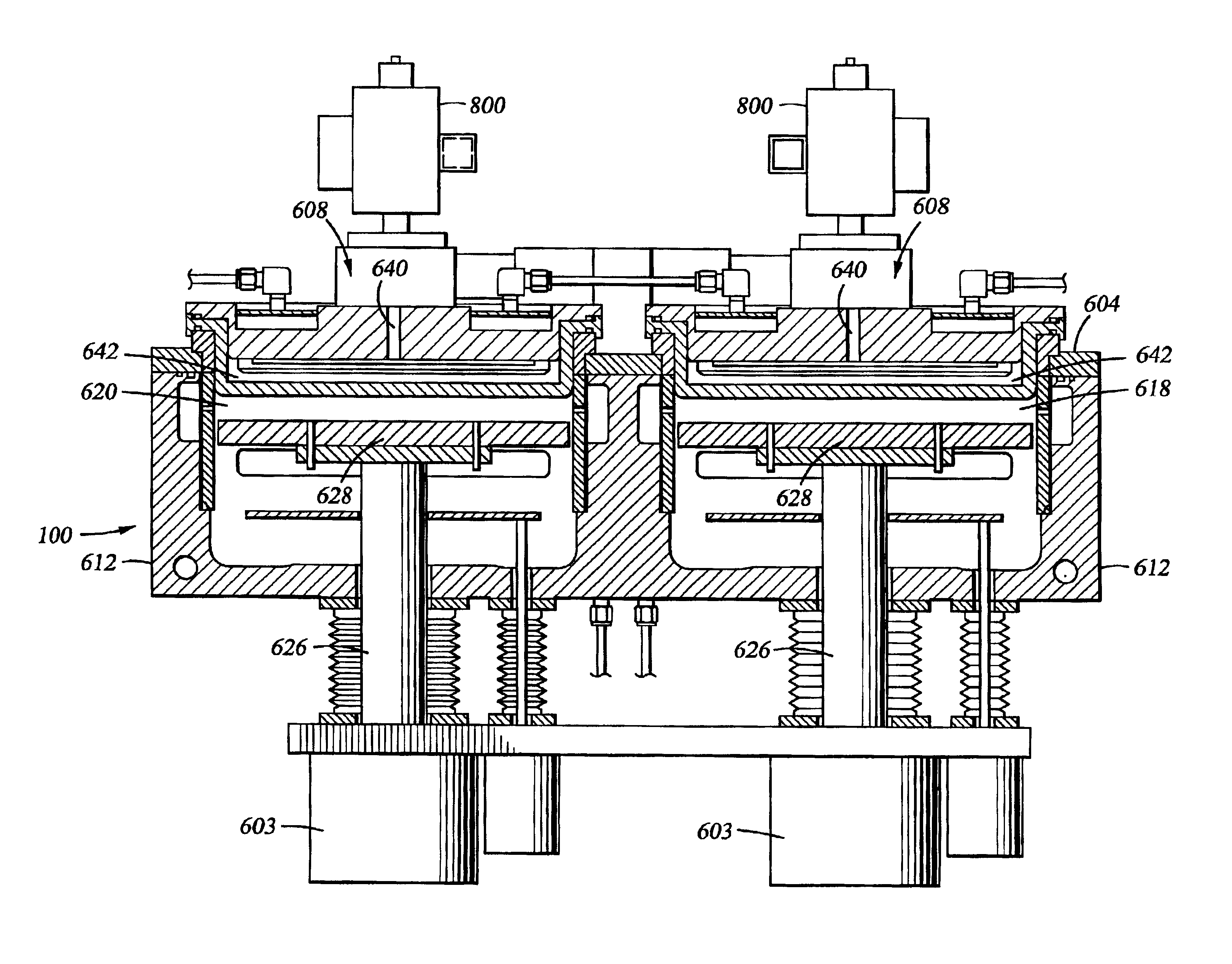
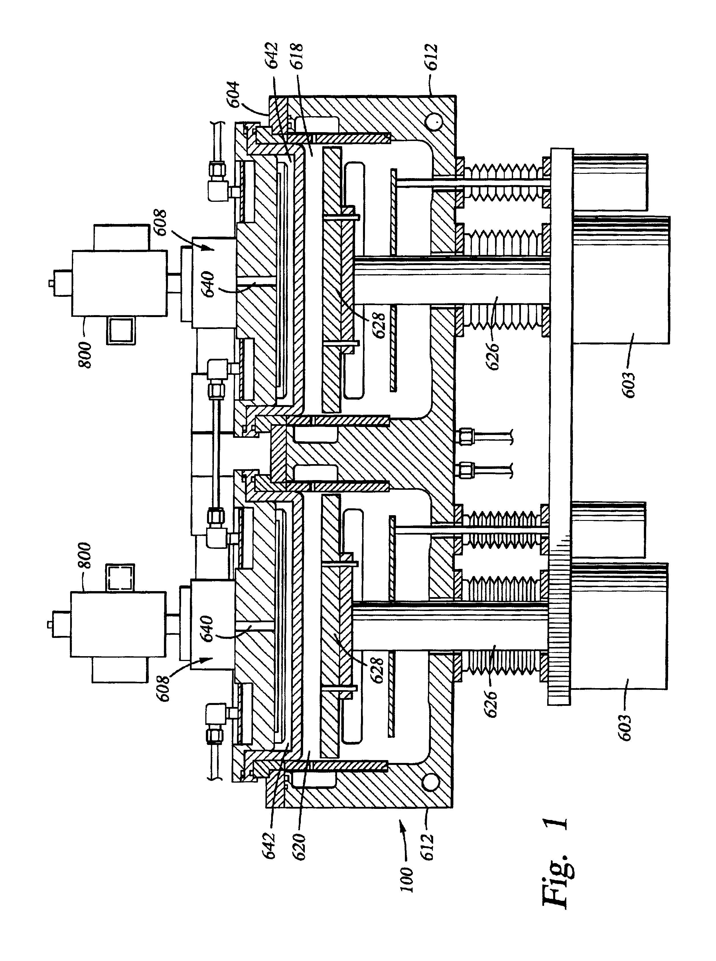

Method for cleaning a process chamber

a technology of process chamber and cleaning method, which is applied in the direction of cleaning hollow objects, cleaning using liquids, coatings, etc., can solve the problems of reducing the number of substrates that can be processed, requiring more time to clean the chamber, and consuming tim

Inactive Publication Date: 2005-06-07
APPLIED MATERIALS INC
View PDF37 Cites 32 Cited by
  • Summary
  • Abstract
  • Description
  • Claims
  • Application Information

AI Technical Summary

Problems solved by technology

However, cleaning a deposition chamber using known remote plasma sources is a time consuming process.
However, more time is required to clean a chamber when a low intensity cleaning process such as a remote plasma clean process is used.
A lengthy chamber cleaning period decreases the number of substrates that can be processed in a given time, since the chamber cannot be used for deposition during the cleaning period.
However, the reactive species often damage the chamber due to the energy imparted to the species in the chamber.
Furthermore, the reactive species can react with the material forming the chamber lining and create undesirable contaminants that may land on and harm a substrate undergoing processing in the chamber.
The removal of contaminating particles from a deposition chamber is becoming increasingly important because the device sizes are becoming smaller and aspect ratios are becoming more aggressive.

Method used


Image

  • Method for cleaning a process chamber
  • Method for cleaning a process chamber

Examples


example 1

[0028]Several hundred sccm of argon was flowed for about two seconds to strike a plasma in two remote plasma sources, model number 5707024-F from Advanced Energy Industries, Inc., connected to a processing region of a Producer® Chamber having experienced a deposition of about 1 μm of Black Diamond™ film, a silicon oxycarbide film available from Applied Materials, Inc. of Santa Clara, Calif., deposited on a substrate within the chamber. NF3 was also introduced into the remote plasma sources. After the plasma was struck, the remote plasma sources delivered about 6 kilowatts of power to the struck plasma. The plasma included free radicals from the NF3. The NF3 was flowed into a processing region of the deposition chamber at a rate of about 900 sccm. Helium was flowed from a separate gas line into the processing region at a rate of about 500 sccm. A radio frequency power of about 250 Watts was delivered to the processing region. The spacing between the electrodes, i.e., the showerhead a...

example 2

[0029]Several hundred sccm of argon was flowed for about two seconds to strike a plasma in two remote plasma sources, model number 5707024-F from Advanced Energy Industries, Inc., connected to a processing region of a Producer® Chamber. NF3 was also introduced into the remote plasma sources. After the plasma was struck, the remote plasma sources delivered about 6 kilowatts of power to the struck plasma. The plasma included free radicals from the NF3. The NF3 was flowed into the processing region at a rate of about 900 sccm. Helium was flowed from a separate gas line into the processing region at a rate of about 500 sccm. A radio frequency power of about 250 Watts was delivered to the processing region. The spacing between the electrodes of the processing region of the chamber was about 400 mils. The chamber was cleaned for about 140 seconds. The radio frequency power was terminated. The flow of helium into the deposition chamber was terminated. NF3 was flowed into the processing reg...


PUM

PropertyMeasurementUnit
poweraaaaaaaaaa
poweraaaaaaaaaa
poweraaaaaaaaaa

Abstract

Methods and apparatus for cleaning deposition chambers are presented. The cleaning methods include the use of a remote plasma source to generate reactive species from a cleaning gas to clean deposition chambers. A flow of helium or argon may be used during chamber cleaning. Radio frequency power may also be used in combination with a remote plasma source to clean deposition chambers.

Description

BACKGROUND OF THE INVENTION[0001]1. Field of the Invention[0002]Embodiments of the present invention generally relate to methods of cleaning a deposition chamber using a remote plasma source.[0003]2. Description of the Related Art[0004]In the fabrication of integrated circuits and semiconductor devices, materials such as oxides are typically deposited on a substrate in a process chamber, such as a deposition chamber, such as a chemical vapor deposition (CVD) chamber. The deposition processes typically result in deposition of some of the material on the walls and components of the deposition chamber. The material deposited on the chamber walls and components can affect the deposition rate from substrate to substrate and the uniformity of the deposition on the substrate.[0005]Several methods of cleaning a deposition chamber have been developed. For example, a remote plasma source can be used to provide a source of free radicals, such as fluorine radicals, that react with deposited mat...

Claims


Application Information

Patent Timeline
Patent Type & Authority Patents(United States)
IPC IPC(8): B08B7/00C23C16/44
CPCB08B7/00C23C16/4405Y10S438/905Y10S134/902
Inventor ZHENG, YISINGH, VINITANEMANI, SRINIVAS D.CHEN, CHEN-ANLEE, JU-HYUNGVENKATARAMAN, SHANKAR
Owner APPLIED MATERIALS INC
Learn More