Ultrahigh pressure discharge lamp of the short arc type with improved metal foil to electrode connection arrangement

a discharge lamp and ultrahigh pressure technology, which is applied in the manufacture of electric discharge tubes/lamps, electrode systems, electrode assembly manufacture, etc., can solve the problems of increased gas escape or crack formation, high pressure within the arc tube during operation, and damage to side tube parts, etc., to suppress the formation and growth of extremely small cracks

Active Publication Date: 2005-06-07
USHIO DENKI KK
View PDF13 Cites 16 Cited by
  • Summary
  • Abstract
  • Description
  • Claims
  • Application Information

AI Technical Summary

Benefits of technology

[0020]In the ultrahigh pressure discharge lamp of the short arc type in accordance with the invention, the above described arrangemen

Problems solved by technology

In such an ultrahigh pressure discharge lamp, the pressure within the arc tube during operation is extremely high.
If they are not arranged tightly adjoining one another, the added gas escapes or cracks form.
However, if the silica glass is heated to an unduly high temperature, the defect arises that, after completion of the discharge lamp, the side tube parts are often damaged, even if the adhesive property of the silica glass on the electrodes or the metal foils is increased.
This causes cracks to form in the area in which the two come into contact with one another.
However, during lamp operation, together with the ultrahigh pressure state du

Method used


Image

  • Ultrahigh pressure discharge lamp of the short arc type with improved metal foil to electrode connection arrangement
  • Ultrahigh pressure discharge lamp of the short arc type with improved metal foil to electrode connection arrangement
  • Ultrahigh pressure discharge lamp of the short arc type with improved metal foil to electrode connection arrangement

Examples


Embodiment Construction

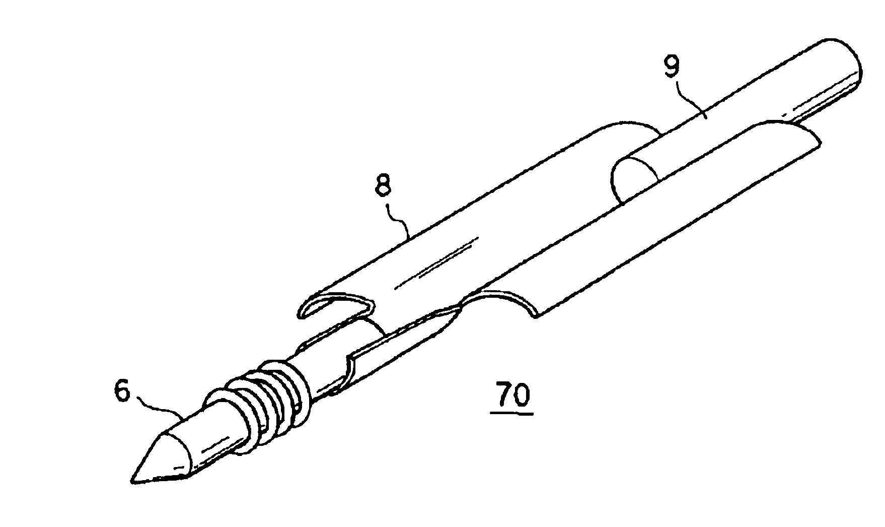
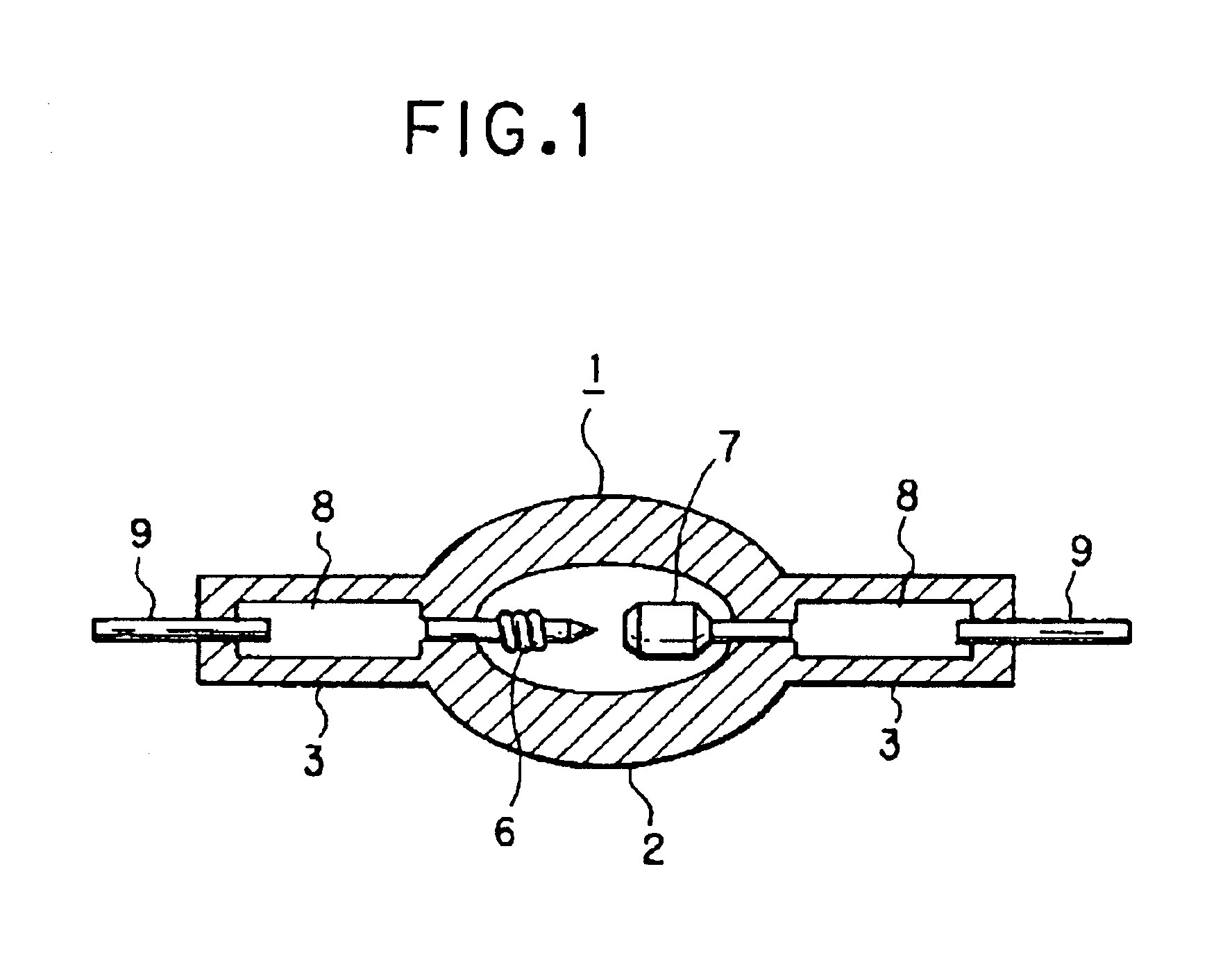
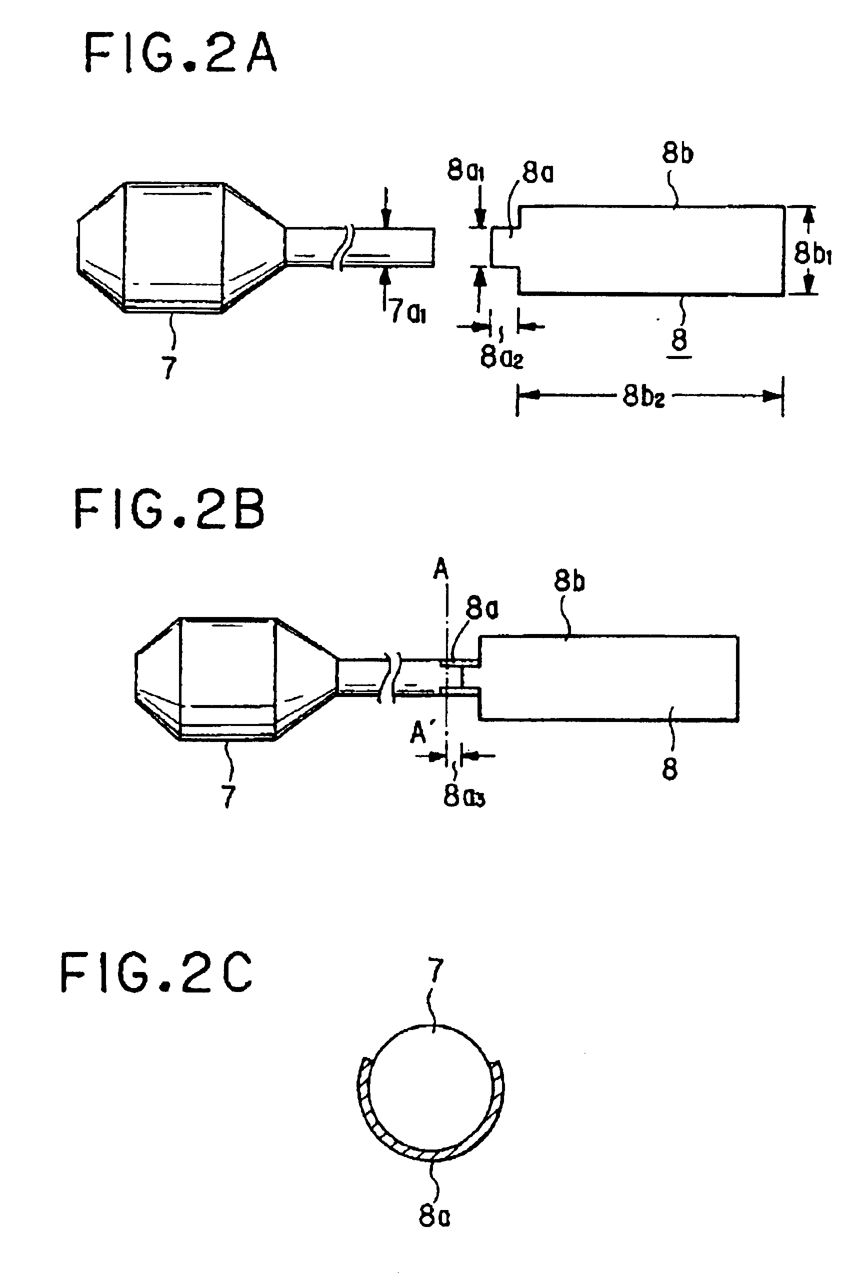
[0035]FIG. 1 shows the overall arrangement of an ultrahigh pressure discharge lamp in accordance with the invention (hereinafter, also called only a “discharge lamp”). In the figure, a discharge lamp 1 has an essentially spherical light emitting part 2 which is formed by a silica glass discharge vessel. Within this light emitting part 2 there are a cathode electrode 6 and an anode electrode 7 disposed opposite on another. A side tube part 3 extends from each the opposite ends of the light emitting part 2. A conductive metal foil 8, which is usually made of molybdenum, is hermetically arranged, for example, by a shrink seal in each side tube part 3. The ends of the cathode and anode electrodes 6, 7 are each located on an end of a respective one of the metal foils 8, and are welded on in this state so as to be are electrically connected to them. An outer lead 9 is welded to the other end of the respective metal foil 8 and projects to out of the side tube part 3. There is certainly a c...


PUM


Abstract

An arrangement with a relatively high pressure tightness in a super-high pressure mercury lamp which is operated with an extremely high mercury vapor pressure is achieved in accordance with the invention in a super-high pressure discharge lamp of the short arc type having a light emitting part in which a pair of electrodes are disposed opposite each other and which is filled with at least 0.15 mg/mm3 mercury; and side tube parts which extend from each side of the light emitting part and in each of which a respective one of the electrodes is partially hermetically sealed and is connected to a metal foil, by the area of the respective metal foil which is connected to the respective electrode has a smaller width than the width in the remaining area of the metal foil, the area with the smaller width wrapping at least partially around the outside surface of the electrode.

Description

BACKGROUND OF THE INVENTION[0001]1. Field of the Invention[0002]The invention relates to an ultrahigh pressure discharge lamp of the short arc type in which the mercury vapor pressure during operation is at least 150 atm. The invention relates especially to an ultrahigh pressure discharge lamp of the short arc type which is used as the back light of a liquid crystal display and for a projector device using a DMD, such as a DLP or the like.[0003]2. Description of Related Art[0004]In a projector device of the projection type, there is a demand for illumination of images onto a rectangular screen in a uniform manner and moreover with adequate color reproduction. Therefore, the light source is a metal halide lamp which is filled with mercury and a metal halide. Furthermore, recently smaller and smaller metal halide lamps, and more and more often point light sources have been produced and lamps with extremely small distances between the electrodes, have been used in practice.[0005]Agains...

Claims


Application Information

Patent Timeline
IPC IPC(8): H01J61/00H01J61/86H01J5/00H01J61/20H01J61/12H01J5/50H01J61/84H01J61/82H01J61/36H01J9/18H01J17/04H01J17/18H01J9/32H01J17/02
CPCH01J61/86H01J61/366
Inventor KANZAKI, YOSHITAKA
Owner USHIO DENKI KK
Why Eureka
Try Eureka