Method for using a motorized camera mount for tracking in augmented reality

Inactive Publication Date: 2005-06-07
INFORMATION DECISION TECH
View PDF6 Cites 18 Cited by
  • Summary
  • Abstract
  • Description
  • Claims
  • Application Information

AI Technical Summary

Benefits of technology

[0007]When using a video camera, it is sometimes useful to superimpose computer-generated graphics onto its view. To accomplish that, this invention uses a video camera with a built-in motor and position encoder to both control and know its position. By using this method, the computer has knowledge of where the camera is looking, thereby allowing the computer to superimpose graphical elements representing real objects, anchored in the real world, onto the view of the camera.

Problems solved by technology

When using a video camera, it is sometimes useful to superimpose computer-generated graphics onto its view.

Method used


Image

  • Method for using a motorized camera mount for tracking in augmented reality
  • Method for using a motorized camera mount for tracking in augmented reality
  • Method for using a motorized camera mount for tracking in augmented reality

Examples


Embodiment Construction

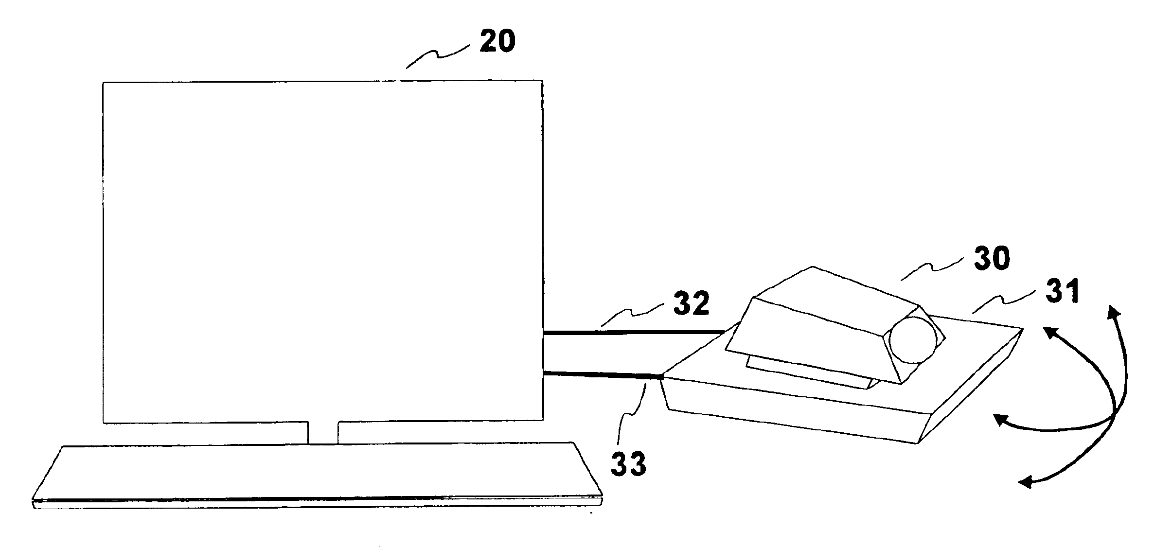
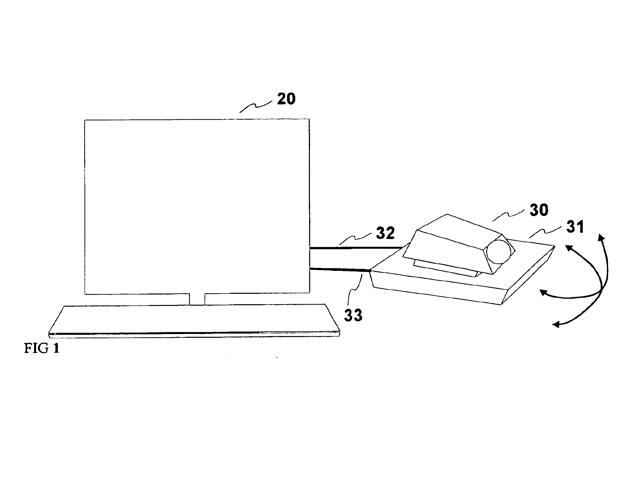
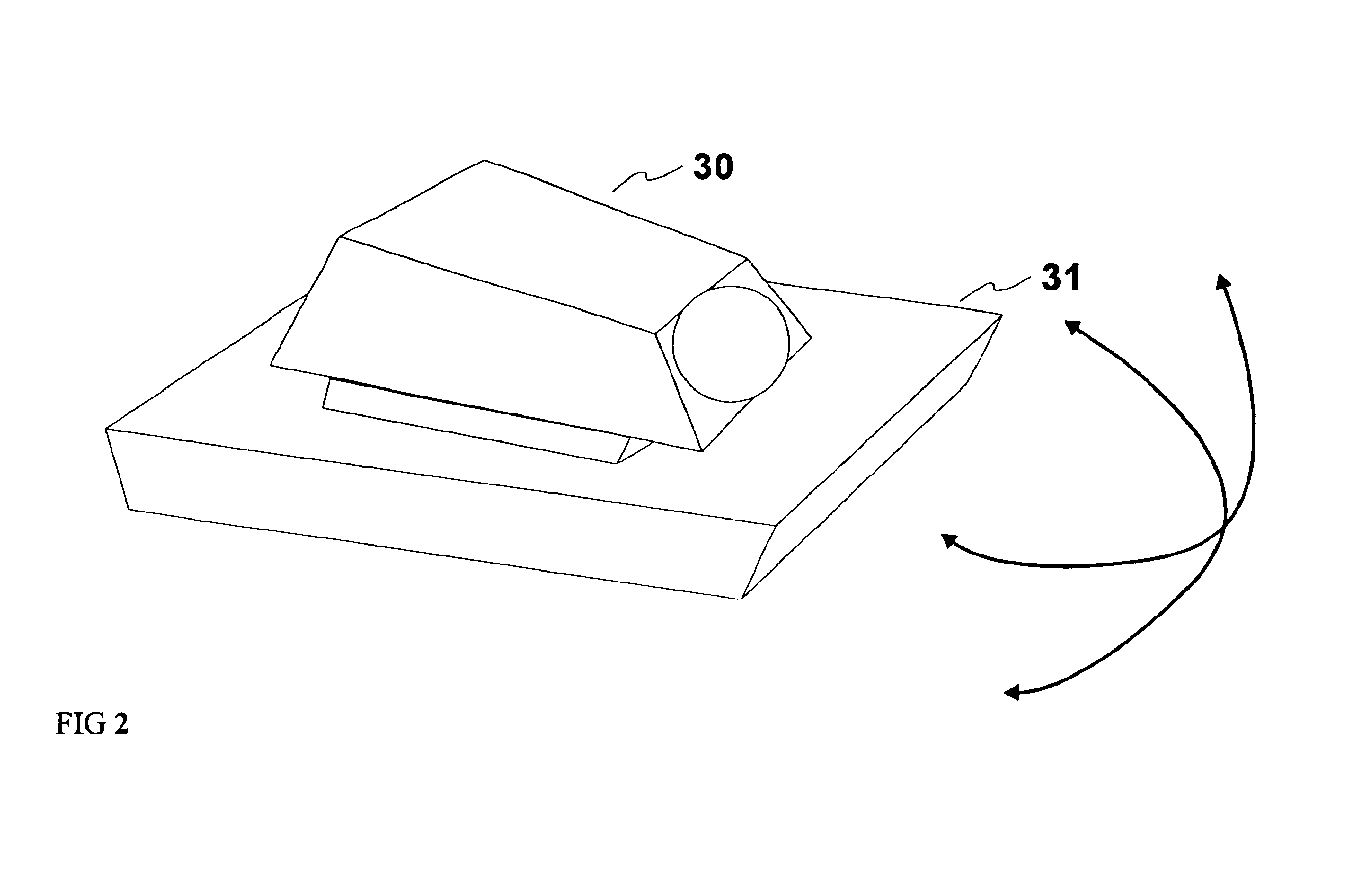
[0018]The preferred embodiment of the invention utilizes a motorized camera mount with a built-in position tracker. The properties of the computer-generated graphical elements are determined by a independent source (e.g., the user, sensor information, or other method of input). The method uses augmented reality (the mixing of real media with computer generated media) to present this information in a format that combines the computer-generated images with the user's real environment. The user then visualizes the combined virtual and real image via a traditional interface such as a computer monitor, or via another method, such as a Head-Mounted Display (HMD).

[0019]The captured video image of the real world is mixed with the computer-generated graphical elements via an onboard or external image combiner to form an augmented reality display. Onboard mixing is performed via software. External mixing can be provided by commercial-off-the-shelf (COTS) mixing hardware, such as a Videonics v...


PUM


Abstract

The invention is a method for displaying otherwise unseen objects and other data using augmented reality (the mixing of real view with computer generated imagery). The method uses a motorized camera mount that can report the position of a camera on that mount back to a computer. With knowledge of where the camera is looking, and the size of its field of view, the computer can precisely overlay computer-generated imagery onto the video image produced by the camera. The method may be used to present to a user such items as existing weather conditions, hazards, or other data, and presents this information to the user by combining the computer generated images with the user's real environment. These images are presented in such a way as to display relevant location and properties of the object to the system user. The primary intended applications are as navigation aids for air traffic controllers and pilots in training and operations, and use with emergency first responder training and operations to view and avoid / alleviate hazardous material situations, however the system can be used to display any imagery that needs to correspond to locations in the real world.

Description

CROSS REFERENCE TO RELATED APPLICATION[0001]This application claims priority of Provisional patent application 60 / 349,028 filed Jan. 15, 2002. This application is a continuation in part of patent application Ser. No. 09 / 634,203, filed on Aug. 9, 2000 now abandoned.FIELD OF THE INVENTION[0002]This invention relates to computer graphics and augmented reality. It defines a way to augment real imagery with a graphical representation of an object (in its actual location) in order to facilitate completion of a task by a human.COPYRIGHT INFORMATION[0003]A portion of the disclosure of this patent document contains material that is subject to copyright protection. The copyright owner has no objection to the facsimile reproduction by anyone of the patent document or the patent disclosure as it appears in the Patent and Trademark Office records but otherwise reserves all copyright works whatsoever.BACKGROUND OF THE INVENTION[0004]This invention can be used any time a user needs to “see” an oth...

Claims


Application Information

Patent Timeline
Patent Type & Authority Patents(United States)
IPC IPC(8): G09G5/00G09B9/00H04N7/00G06F3/01G06T15/10G06T15/20G06T19/00
CPCG06F3/011G06T15/10H04N5/232G06T19/006G09G2340/125G06T15/20H04N23/63H04N23/695
Inventor HOBGOOD, ANDREW W.EBERSOLE, JR., JOHN F.WALKER, JOHN F.EBERSOLE, JOHN F.
Owner INFORMATION DECISION TECH
Why Eureka
Try Eureka