
Resolution enhanced optical spectrometer having a fixed number of photodetector elements

a technology of optical spectrometer and photodetector, which is applied in the field of integrated optical spectrometer, can solve the problems of inability to meet the requirements of in situ applications or installation within fibre optic networks, low resolution of spectrometer, and large cos

Inactive Publication Date: 2005-06-07
ENABLENCE
View PDF3 Cites 21 Cited by
  • Summary
  • Abstract
  • Description
  • Claims
  • Application Information

AI Technical Summary

Problems solved by technology

Unfortunately, these spectrometers described above are large and costly.
As such, they are not well suited to in situ applications or to installation within fibre optic networks.
In a first approach, fewer photo detectors are employed resulting in lower resolution of the spectrometer.
However because these devices have moving parts they are costly, difficult to manufacture, require re-calibration at frequent intervals and, as such, are not preferable for use in optical networks.
In the second approach, smaller optical components are used resulting in insufficient dispersion of light incident on the photo detectors.
The resolution of the spectrometer is limited by the spacing of the photo detectors in the array.
This is problematic since smaller detectors are typically more costly and less sensitive.

Method used


Image

  • Resolution enhanced optical spectrometer having a fixed number of photodetector elements
  • Resolution enhanced optical spectrometer having a fixed number of photodetector elements
  • Resolution enhanced optical spectrometer having a fixed number of photodetector elements

Examples


Embodiment Construction

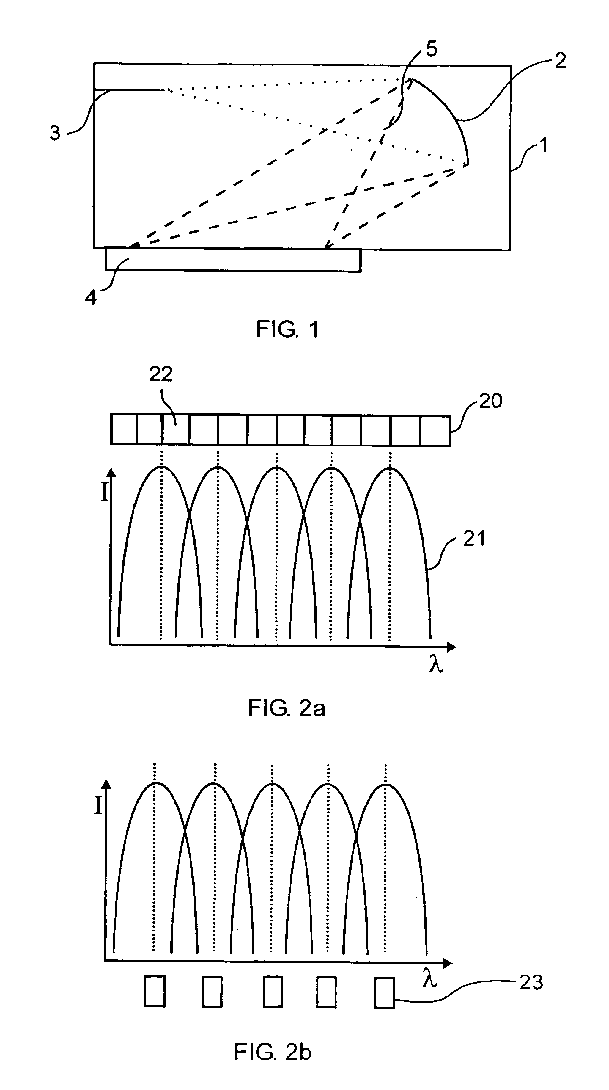
[0057]Referring to FIG. 1, a spectrometer 1 integrated within a planar waveguide is shown incorporating a waveguide grating 2. The spectrometer 1 is for dispersing light incident thereon in dependence upon a wavelength of the light. In order to accomplish this, light is provided at an input port to a waveguide 3. The waveguide 3 is coupled to a slab waveguide region for providing the received light thereto. The light expands within the two dimensional slab waveguide region 5 and is then incident on the waveguide grating 2. Though a reflective echelle grating is shown, the grating is optionally another form of grating. The grating acts to adjust a phase of the light incident thereon in order to cause light to disperse across an output port in dependence upon its wavelength such that light at a first wavelength is incident at a first predetermined location and light at a second other wavelength is incident at a second other predetermined location. A plurality of photodetectors 4 are d...


PUM


Abstract

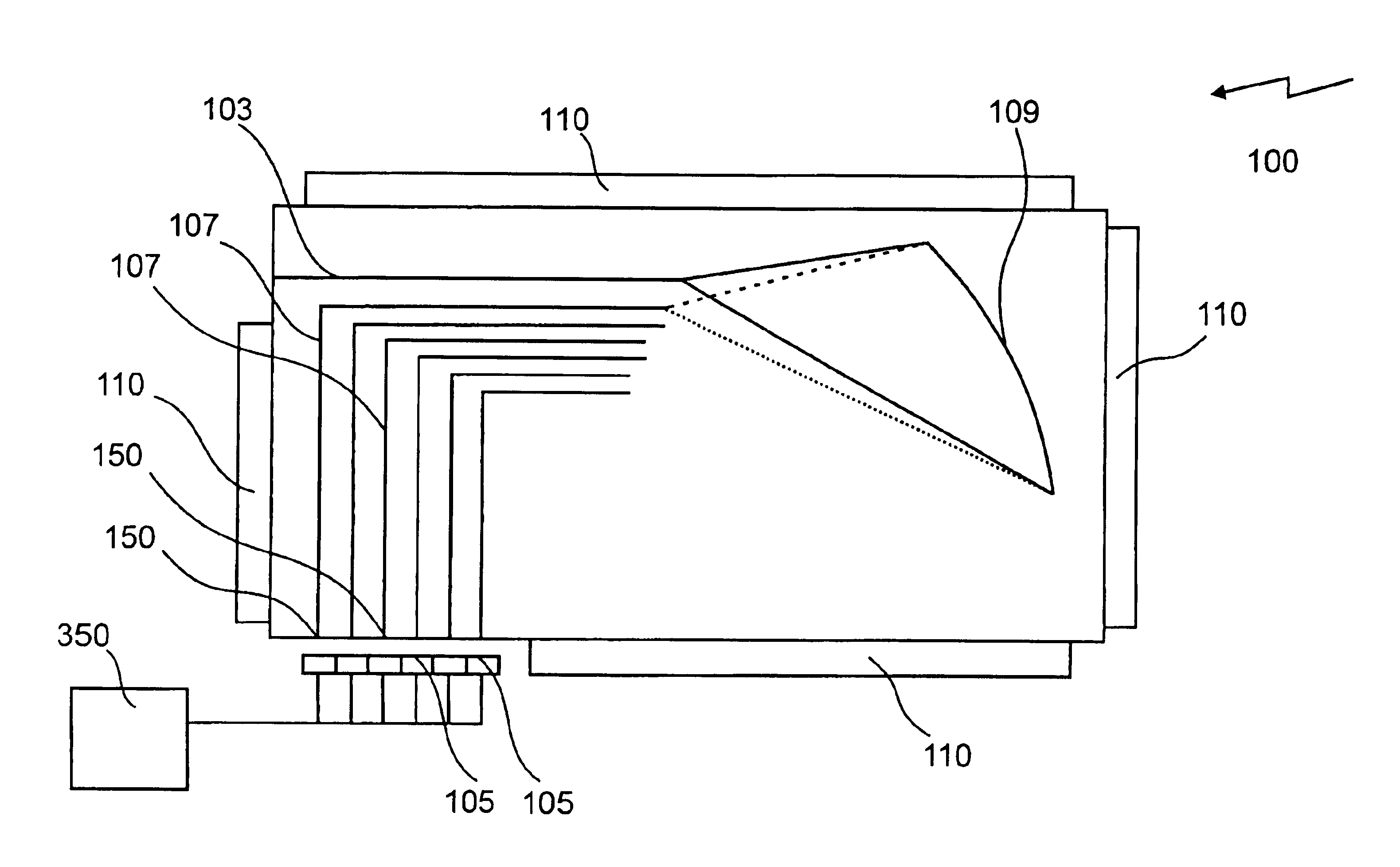
A waveguide optical monitor is disclosed. The device has an optical input port coupled through a switch to a plurality of input waveguides. A dispersive element disperses light within the input optical waveguides toward a plurality of output waveguides. There are a plurality of photodetectors each optically coupled to an output waveguide. The photodectors are for sensing an intensity of light within the waveguide with which it is optically coupled. An optical switch in optical communication with the optical input port and for switching light received at the optical input port to one of the plurality of input waveguides. Also, an angular dispersive element is present for receiving light from any one of the waveguides and for dispersing the light toward a plurality of output waveguides in dependence upon the input waveguide position and a wavelength of the light such that light directed from the first of the plurality of input waveguides toward the plurality of output waveguides has a first centre wavelength within each of the output waveguides and light directed from the second of the plurality of input waveguides toward the plurality of output waveguides has a second different centre wavelength within each of the output waveguides, the second different center wavelength different form any first center wavelength.

Description

[0001]This application is a divisional application of U.S. patent application Ser. No. 10 / 102,833 filed Mar. 22, 2002 now U.S. Pat. No. 6,753,958, which claims the benefit of U.S. Provisional Application No. 60 / 277,629 filed Mar. 22, 2001, now abandoned.FIELD OF THE INVENTION[0002]The invention generally relates to integrated optical spectrometers and more specifically to an optical spectrometer with enhanced resolution.BACKGROUND OF THE INVENTION[0003]Optical spectrometers are devices that separate an optical signal into a plurality of component optical signals based on a wavelength of each component. Thus, a spectrometric device allows for accurate measurement of light within separate wavelength ranges or channels. The measurement of this light allows for determinations to be made about the light being analysed.[0004]It is well known to photograph a spectrum produced by passing light through a gaseous sample in order to classify the sample. In high school chemistry text books, rea...

Claims


Application Information

Patent Timeline
Patent Type & Authority Patents(United States)
IPC IPC(8): G02B6/12G02B6/34G01J3/02G01J3/00G01J3/18
CPCG02B6/4215G01J3/18G02B6/12007G01J3/0256G01J3/0259G01J3/0294
Inventor BEROLO, ORAZIOHE, JIAN-JUNKOTELES, EMIL S.HICHWA, BRYANTWADE, JOHN
Owner ENABLENCE
Learn More