
Multi-channel dual phase lock-in optical spectrometer

a dual-phase lock-in, optical spectrometer technology, applied in the field of optical spectroscopy, can solve the problems of inconvenient parallelization of lock-in techniques, limited frequency range, and less effective bandwidth narrowing methods

Inactive Publication Date: 2008-02-26
PITTSBURGH UNIV OF
View PDF10 Cites 2 Cited by
  • Summary
  • Abstract
  • Description
  • Claims
  • Application Information

AI Technical Summary

Benefits of technology

"The invention is an optical system that uses a light deflector to move light in a certain direction over time. It also has a spectrometer that separates light based on its wavelength. The system has a focal plane array that detects the separated light and the light that is moving as a function of time. The technical effect of this invention is that it allows for the detection of light in two different directions, making it more versatile and efficient."

Problems solved by technology

However, the spectral response of such a technique is functionally equivalent to a comb filter and thus is less effective than bandwidth narrowing methods that use true lock-in amplification.
Furthermore, the range of frequencies available is limited by the frame rate which is usually quite low compared to the frequencies at which one would like to operate.
However, due to the high photon fluxes and large backgrounds, it is not straightforward to parallelize lock-in techniques.
Banks of up to 32 digital lock-in channels are commercially available (http: / / www.signalrecovery.com), but for a reasonable number of channels (e.g., 256 or 512), this approach quickly becomes financially burdensome and unwieldy.

Method used


Image

  • Multi-channel dual phase lock-in optical spectrometer
  • Multi-channel dual phase lock-in optical spectrometer
  • Multi-channel dual phase lock-in optical spectrometer

Examples


Embodiment Construction

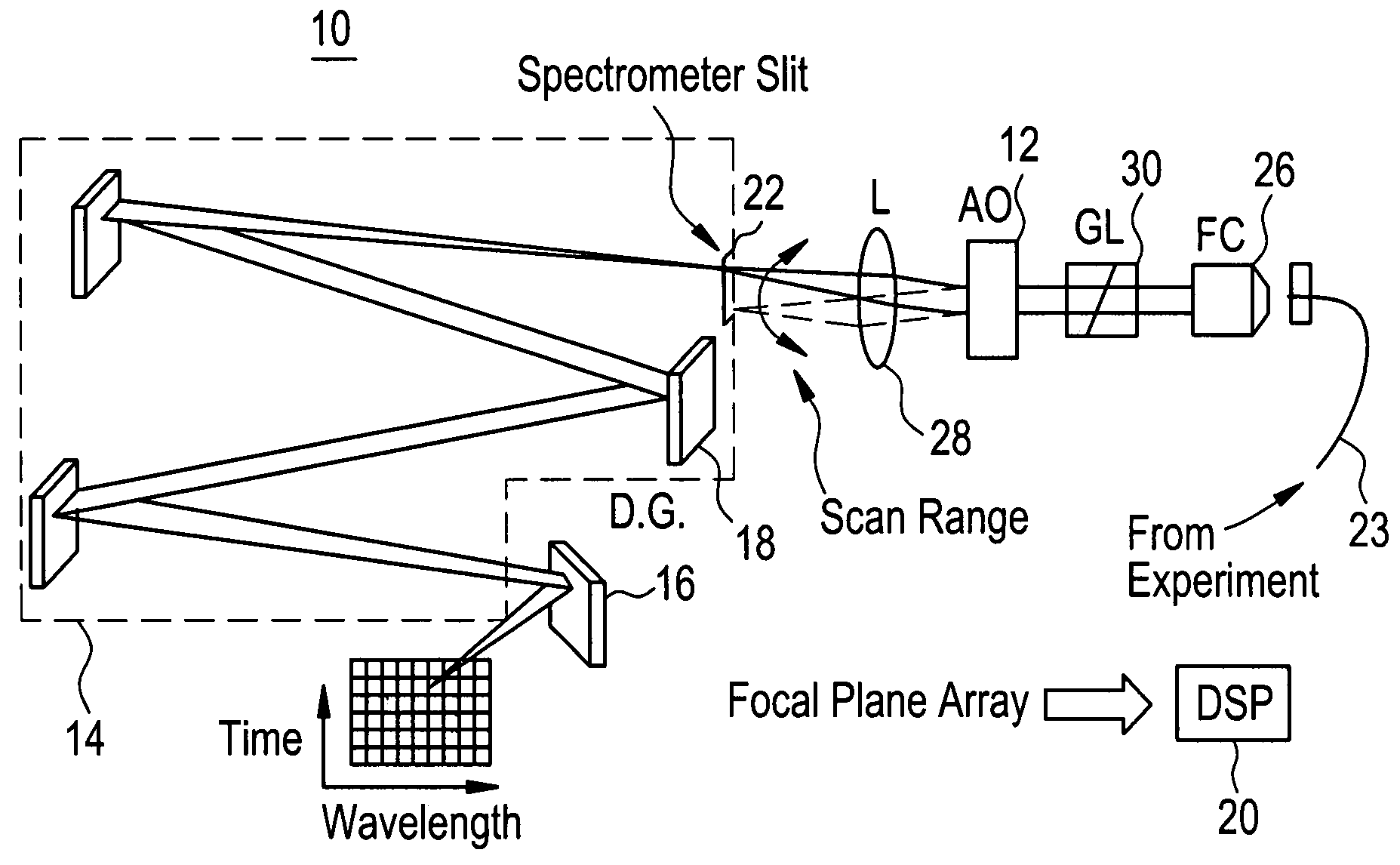
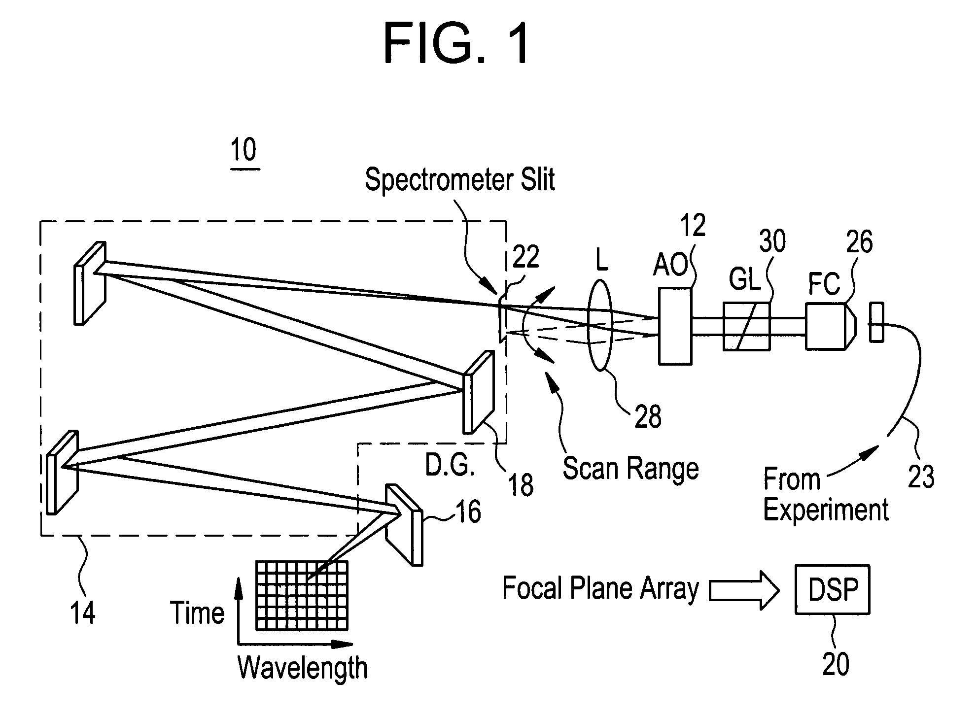
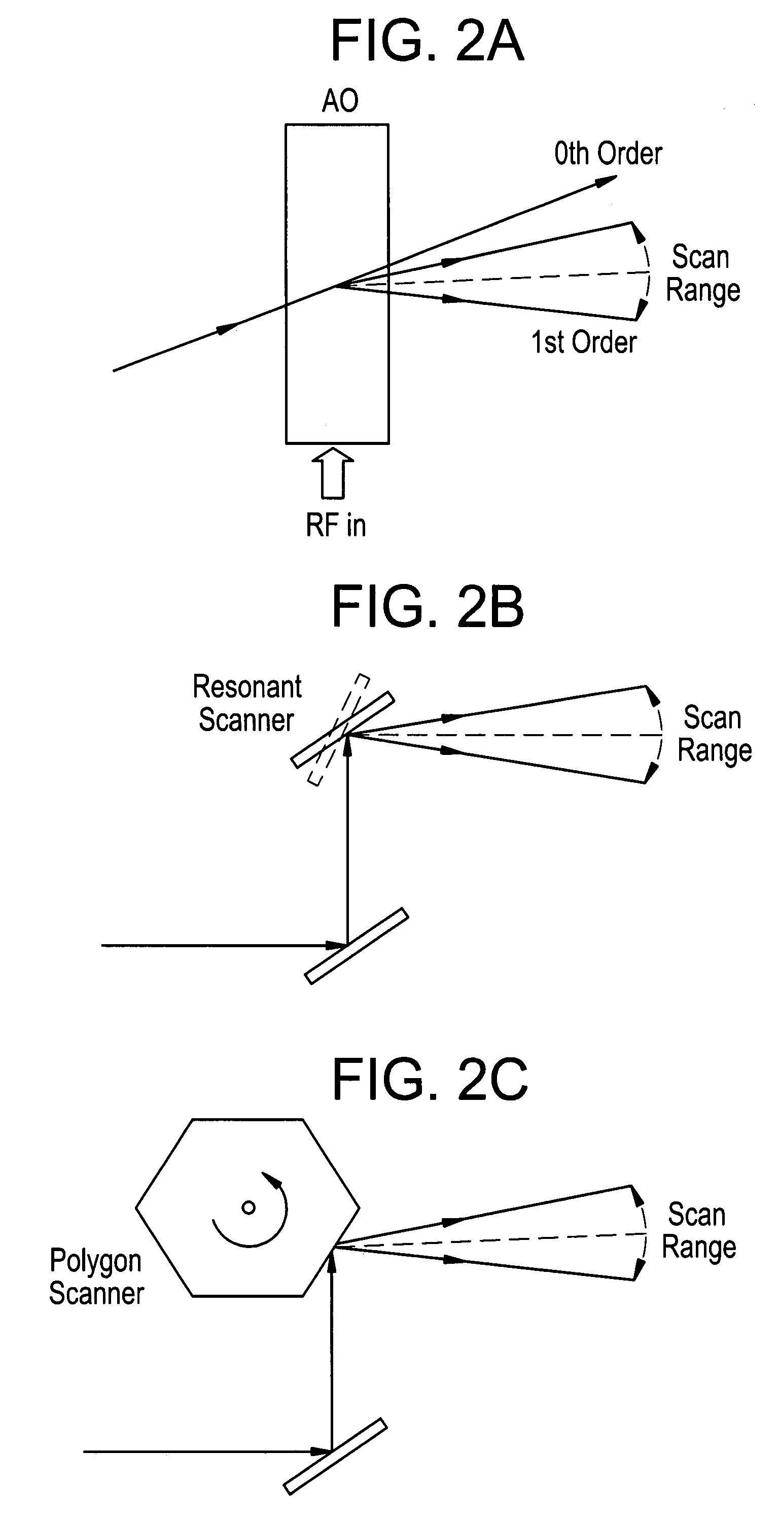
[0018]An optical system 10 of the first embodiment is shown in FIG. 1. The system includes a light deflector 12 which is adapted to deflect light in a particular direction as a function of time. For example, this may be a vertical direction. However, other directions, such as horizontal may also be used. The system 10 also includes a spectrometer 14 which is adapted to separate light according to wavelength in a direction which is different from the direction of the light deflected by the light deflector. For example, if the deflector 10 deflects the light in a vertical direction, then the spectrometer may separate the deflected light in a horizontal direction. However, other separation directions are also possible. The system also contains a two dimensional photodetector array 16, which is generally referred to herein as a focal plane array.

[0019]The focal plane array 16 is adapted to detect the light separated according to wavelength by the spectrometer 14 along a first direction ...


PUM


Abstract

The development of a multiple-channel dual phase lock-in optical spectrometer (LIOS) is presented, which enables parallel phase-sensitive detection at the output of an optical spectrometer. The light intensity from a spectrally broad source is modulated at the reference frequency, and focused into a high-resolution imaging spectrometer. The height at which the light enters the spectrometer is controlled by an acousto-optic deflector, and the height information is preserved at the output focal plane. A two-dimensional InGaAs focal plane array collects light that has been dispersed in wavelength along the horizontal direction, and in time along the vertical direction. The data is demodulated using a high performance computer-based digital signal processor. This parallel approach greatly enhances (by more than 100×) the speed at which spectrally resolved lock-in data can be acquired.

Description

CROSS-REFERENCE TO RELATED PATENT APPLICATIONS[0001]This application claims benefit of priority of U.S. Provisional Application Ser. No. 60 / 601,136, filed on Aug. 13, 2004 and is incorporated herein by reference in its entirety.[0002]The U.S. government may have certain rights in this invention pursuant to DARPA grant number DAAD 10-01-1-0650.BACKGROUND OF THE INVENTION[0003]This invention is related to optical spectroscopy, specifically to a lock-in optical spectrometer system.[0004]Optical spectroscopy is a pervasive tool across physical, chemical and biological sciences. In a typical spectrometer, the light focused on the entrance slit is dispersed by a diffraction grating which spatially separates the light according to wavelength. Spectroscopic information is obtained by scanning the angle of the diffraction grating, and allowing different wavelengths to pass through an exit slit. The availability of photodetectors, such as one dimensional charge-coupled device (CCD) and two di...

Claims


Application Information

Patent Timeline
Patent Type & Authority Patents(United States)
IPC IPC(8): G01J3/06G01J3/18G01J3/28
CPCG01J3/1256G01J3/2803G01J3/2823G01J3/2889G01J3/433G01J3/0294G01J2001/4242
Inventor LEVY, JEREMY
Owner PITTSBURGH UNIV OF
Learn More