
An optical spectrometer based on swinging reflector and transmission grating
A transmission grating and spectrometer technology, applied in the field of spectrometers, can solve the problems of high cost and large volume, and achieve the effects of price reduction, instrument volume reduction, and simplified structure
Patent Information
- Authority / Receiving Office
- CN · China
- Patent Type
- Applications(China)
- Current Assignee / Owner
- Publication Date
- 2009-10-07
- Estimated Expiration
- Not applicable · inactive patent
Smart Images
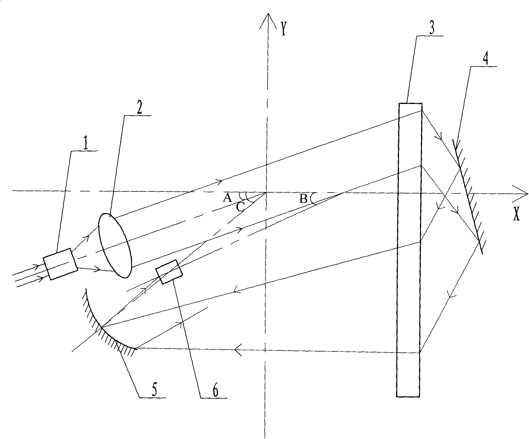
Figure 1
Abstract
Description
technical field
[0001] The invention relates to a spectrometer, in particular to a spectrometer based on a swing mirror and a transmission grating. Background technique
[0002] As an important analysis method, spectral analysis method plays a great role in scientific research, production, quality control, etc., and obtaining single-wavelength radiation is an indispensable means. At present, the CCD (Charge Coupled Device) multi-channel spectrometer with multi-channel detectors, which is widely used in the online detection of industrial processes, adopts a transmission grating structure. on the multichannel detector. In order to improve the spectral resolution ability, the transmission grating must adopt high-density grooves, but at the same time, in order to ensure the diffraction efficiency of the grating, for the near-infrared band of 1000nm-1800nm, the number of lines of the grating grooves is generally selected as 600 lines / mm or 300 lines / mm It is more suitable, but ...
Examples
specific Embodiment approach 1
[0008] Specific implementation mode one: the following combination figure 1 Describe this embodiment, this embodiment is made up of incident optical fiber 1, lenticular lens 2, plane transmission grating 3, swing reflector 4, concave reflector 5 and near-infrared detector 6, and the back surface of plane transmission grating 3 has grating engraving The light beam passing through the incident fiber 1 is incident into the lenticular lens 2, and the parallel light is transmitted through the lenticular lens 2 to obtain parallel light. After the second light splitting, it enters into the swinging mirror 4, and the light reflected by the swinging mirror 4 is incident on the rear surface of the plane transmission grating 3, and after being scored by the grating for the second splitting, the light is incident on the concave reflecting mirror 5 through the front surface , the light reflected by the concave reflector 5 is received by the input end of the near-infrared detector 6; the pl...
specific Embodiment approach 2
[0011] Embodiment 2: The difference between this embodiment and Embodiment 1 is that the grating score specification of the planar transmission grating 3 is 600 lines / mm. Other components and connections are the same as those in Embodiment 1.
[0012] The number of grating score lines of the planar transmission grating 3 is the same as the prior art and selects 600 lines / mm. While ensuring the diffraction efficiency, the resolution is doubled due to two light splits; Under the same situation in the prior art, the resolution of the present invention is higher than the spectrometer that adopts multi-channel detectors; under the same situation as the conventional transmission grating spectrometer in resolution, the focal length selection of the concave reflector 5 can be shortened by one time, and the instrument The volume is greatly reduced.
specific Embodiment approach 3
[0013] Specific embodiment three: the difference between this embodiment and embodiment one or two is that the coordinates of the center of the incident optical fiber 1 on the plane coordinate system are (10, 3.6), and the double-convex lens 2 is close to the mirror center of the incident optical fiber 1 port side The coordinates are (7.6, 2.8), the center coordinates of the plane transmission grating 3 close to the oscillating mirror 4 are (0, 2), the mirror center coordinates of the oscillating mirror 4 are (-1.5, 0.6), and the concave surface of the concave mirror 5 is The coordinates of the center of the near-infrared detector 6 are (6.9, 10.3), and the coordinates of the center of the photosensitive element of the near-infrared detector 6 are (0, 6.8). Other compositions and connections are the same as those in the first or second embodiment.