Optical waveguide modulator

An optical waveguide and modulator technology, applied in the field of optical waveguide modulators, can solve the problems of poor resonant spectral line steepness, difficult to achieve high-efficiency adjustment, and narrow modulation wavelength range, so as to increase the wavelength range, reduce drift effects, and achieve high efficiency. The effect of coupling adjustment

Inactive Publication Date: 2011-11-23
PEKING UNIV
View PDF1 Cites 7 Cited by
  • Summary
  • Abstract
  • Description
  • Claims
  • Application Information

AI Technical Summary

Problems solved by technology

However, since the current ring waveguide modulator realizes intensity modulation based on the principle of spectral line drift, the problem is: high optical modulation efficiency (wherein: optical modulation efficiency=output light intensity change / modulated waveguide refractive index change), for The requirement for optical characteristics is a steep resonance line, and the corresponding modulation wavelength range is narrow; if a wider modulation wavelength range is required, the corresponding resonance line is poor in steepness, and the modulation efficiency decreases
However, efficient adjustment of the coupling coefficient is difficult to achieve in a small-sized waveguide structure, so an efficient coupling modulation method is the key to further improving the modulation efficiency, so as to realize the integrated high-speed waveguide modulator currently required

Method used


Image

  • Optical waveguide modulator
  • Optical waveguide modulator
  • Optical waveguide modulator

Examples


Embodiment Construction

[0025] The specific implementation manners of the present invention will be further described in detail below in conjunction with the accompanying drawings and embodiments. The following examples are used to illustrate the present invention, but are not intended to limit the scope of the present invention.

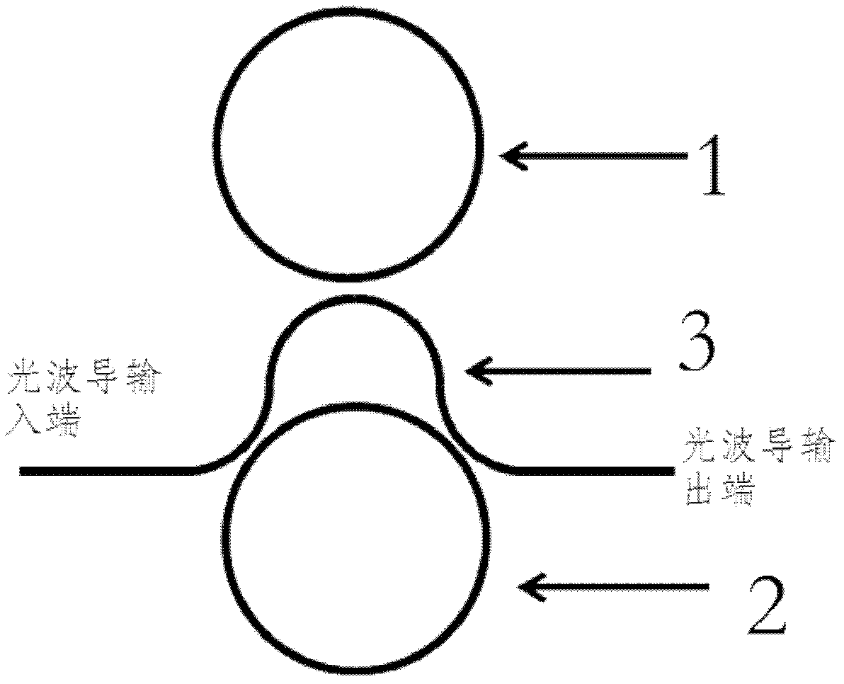
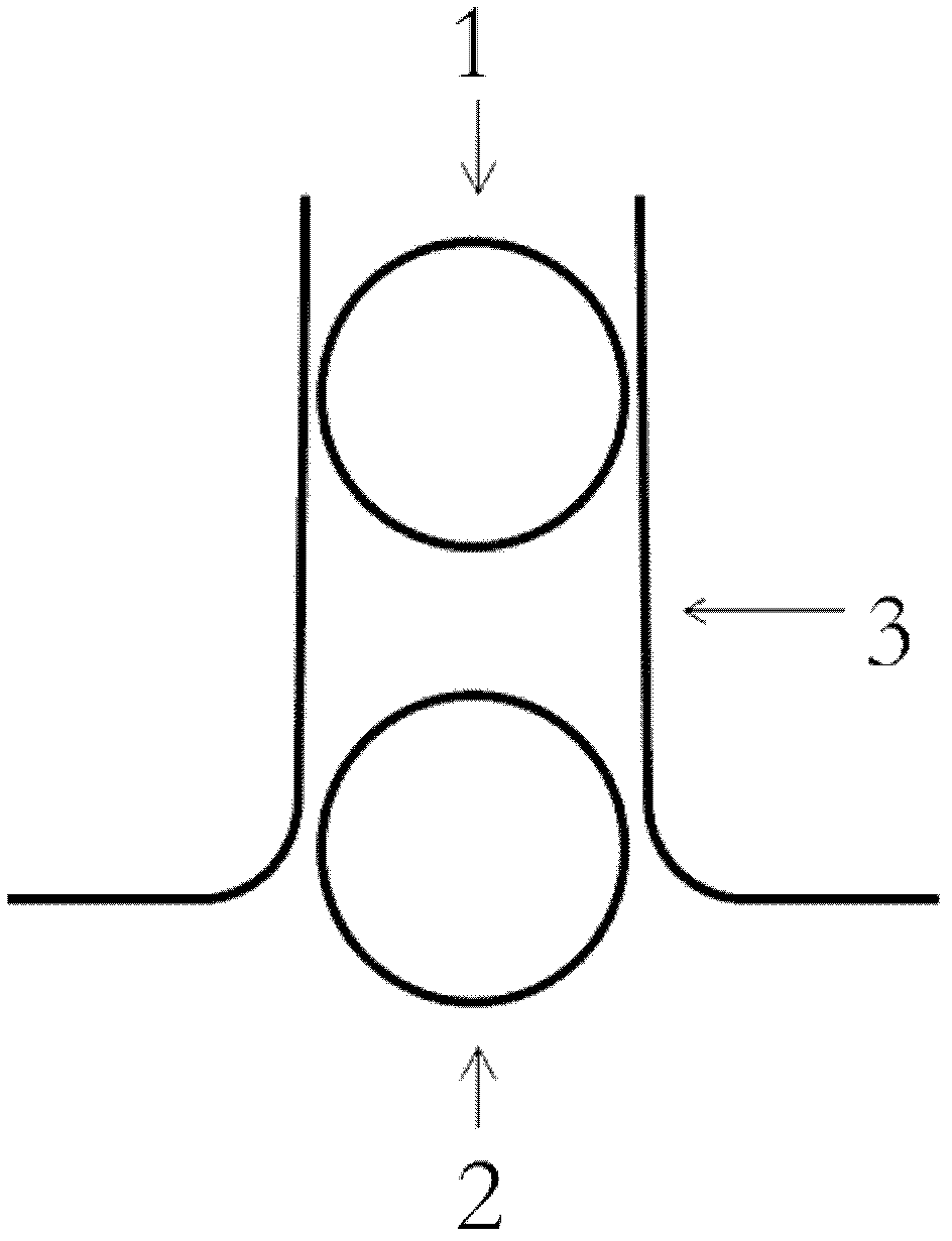
[0026] Such as Figure 1-2 As shown, the optical waveguide modulator provided by the embodiment of the present invention includes: a modulation area 1, a wavelength selection area 2 and a connection area 3;

[0027] The modulation area 1 is a resonant cavity structure, which uses physical reactions to change the refractive index of the optical waveguide, and the refractive index of the optical waveguide and its phase change have a nonlinear relationship. The wavelength selection region 2 is a closed optical waveguide structure, and the resonant wavelength is selected by an interference method. The modulation area 1 and the wavelength selection area 2 transmit their optic...


PUM


Abstract

The invention relates to the technical field of optical modulators, and particularly relates to an optical waveguide modulator. The optical waveguide modulator comprises a modulation area, a wavelength selection area and a connection area, wherein the modulation area is in a resonant cavity structure and used for changing the refractive index of an optical waveguide through a physical reaction, and a nonlinear relation is formed between the refractive index and phase change of the optical waveguide; the wavelength selection area is in a closed optical waveguide structure and used for carrying out selection on resonance wavelengths by using an interference method; and the modulation area and the wavelength selection area are subjected to optical signal transmission by the connection area. By using the the optical waveguide modulator provided by the invention, a nonlinear change relation between a refractive index and a coupling coefficient can be realized by a special coupling structure, and the reduction on the size of the modulator can be realized while high-efficiency coupling regulation is carried out. Compared with the existing optical waveguide modulator, the modulation efficiency ratio of the optical waveguide modulator provided by the invention is over 10 times as large as the existing optical waveguide modulator; and because the modulation area is isolated from the wavelength selection area, the drift influence (caused by an active thermal effect) on operation wavelengths is reduced.

Description

technical field [0001] The invention relates to the technical field of optical modulators in optical communication technology, in particular to an optical modulator. Background technique [0002] At present, silicon photonics, which combines photon technology and microelectronics technology to achieve silicon-based optoelectronic integration, has become a very popular frontier science in the field of optoelectronics in the world. Silicon photonics components include light sources, optical waveguides, photonic crystals, optical switches, optical amplifiers, optical modulators, and optical detectors. Among them, the optical modulator can load information onto the optical carrier for transmission, and is one of the important components in the field of optical communication. Ring waveguide resonators have the characteristics of small size and high resonance quality factor, and are widely used in optoelectronic integration. Since their wavelength selectivity is very sensitive t...

Claims


Application Information

Patent Timeline
Patent Type & Authority Applications(China)
IPC IPC(8): G02F1/365
Inventor 周治平易华祥王兴军
Owner PEKING UNIV
Why Eureka
Try Eureka