Waterflood control system for maximizing total oil recovery

a control system and waterflood technology, applied in the field of secondary oil recovery by waterflooding, can solve the problems of failed, dead, or lost well, and no longer useful function of injectors,

Inactive Publication Date: 2005-06-07
RGT UNIV OF CALIFORNIA
View PDF10 Cites 45 Cited by
  • Summary
  • Abstract
  • Description
  • Claims
  • Application Information

AI Technical Summary

Benefits of technology

[0019]an output device for controlling the injector well injection pressure, whereby the injec

Problems solved by technology

Improper management of waterfloods can create permanent, irreparable damage to well fields that can trap oil so that subsequent waterflooding becomes futile.
The growth of such hydrofractures can cause a direct conduit from an injector to a producer, whereby no further oil is produced, and water is simply pumped in the injector, conducted through the hydrofractured conduit, and recovered at the producer through a process known as “channeling.” At this juncture, the injector is no longer useful in its function, and is now known as a failed

Method used


Image

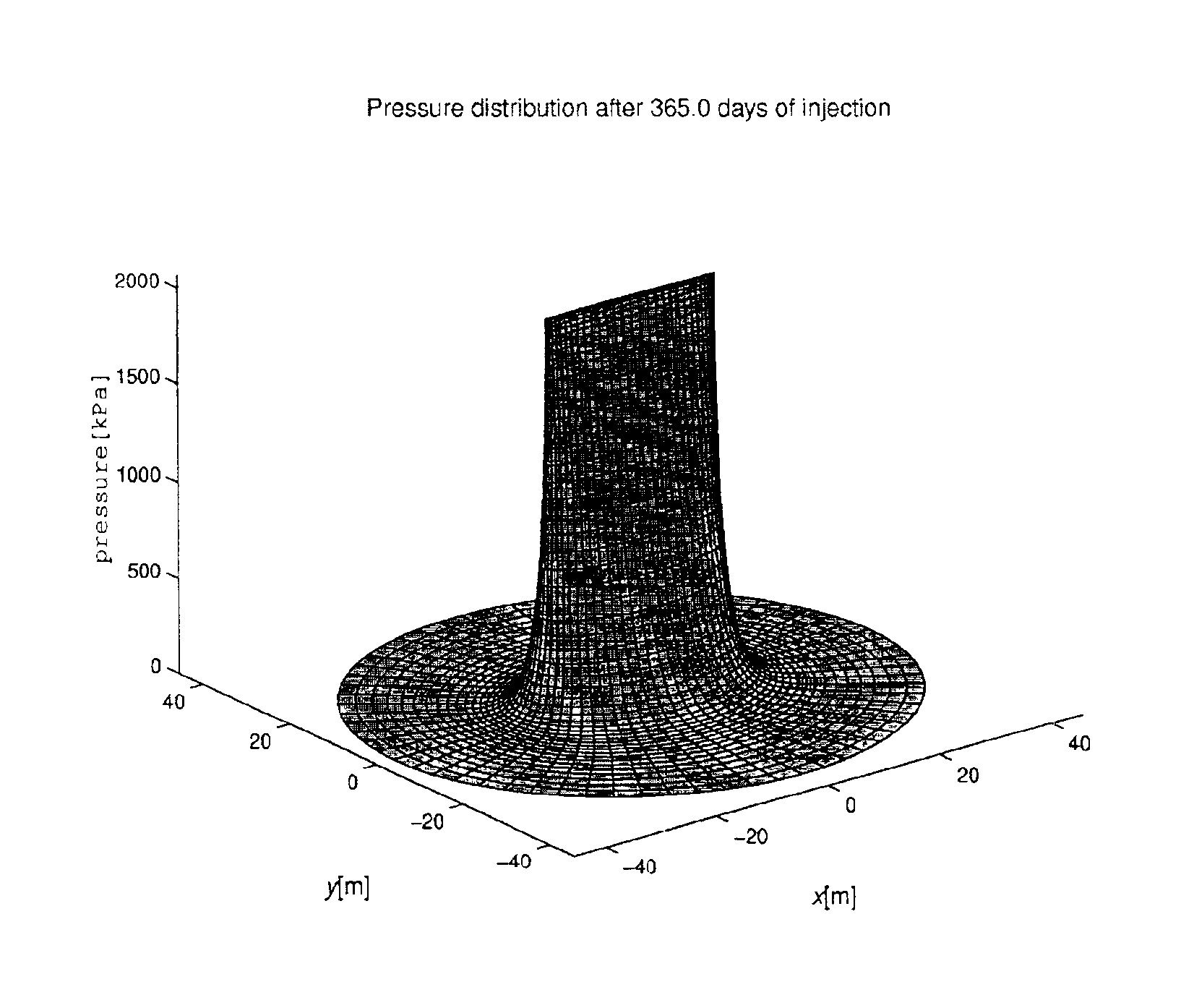
  • Waterflood control system for maximizing total oil recovery
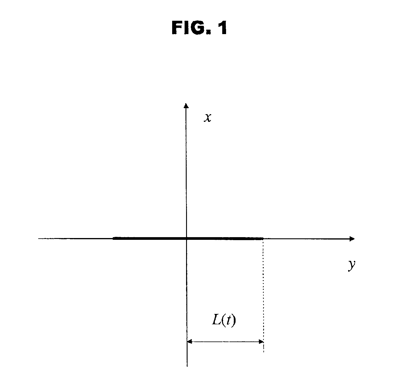
  • Waterflood control system for maximizing total oil recovery
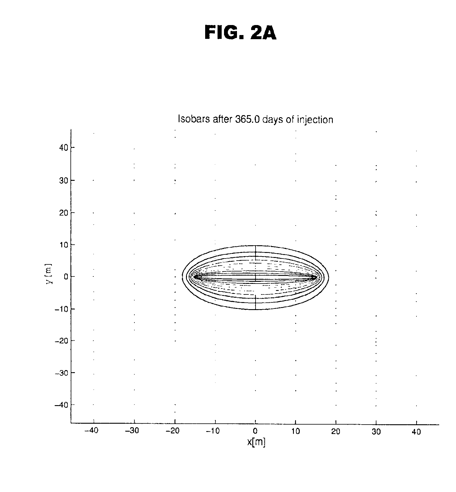
  • Waterflood control system for maximizing total oil recovery

Examples


Embodiment Construction

[0056]The following references are hereby specifically incorporated in their entirety by attachment to this specification and each describe part of the means for performing the process described herein:[0057]“Control Model of Water Injection into a Layered Formation”, Paper SPE 59300, Accepted by SPEJ, December 2000, Authors: Silin and Patzek;[0058]“Waterflood Surveillance and Supervisory Control”, Paper SPE 59295, Presented at the 2000 SPE / DOE Improved Oil Recovery Symposium held in Tulsa, Okla., 3-5Apr., 2000;[0059]“Transport in Porous Media, TIPM 1493”, Water Injection Into a Low-Permeability Rock—1. Hydrofracture Growth, Authors: Silin and Patzek;[0060]“Transport in Porous Media, TIPM 1493”, Water Injection Into a Low-Permeability Rock—2. Control Model, Authors: Silin and Patzek; and[0061]“Use of InSAR in Surveillance and Control of a Large field Project” Authors: Silin and Patzek.

Defined Terms

[0062]Computer: any device capable of performing the steps developed in this invention...


PUM


Abstract

A control system and method for determining optimal fluid injection pressure is based upon a model of a growing hydrofracture due to waterflood injection pressure. This model is used to develop a control system optimizing the injection pressure by using a prescribed injection goal coupled with the historical times, pressures, and volume of injected fluid at a single well. In this control method, the historical data is used to derive two major flow components: the transitional component, where cumulative injection volume is scaled as the square root of time, and a steady-state breakthrough component, which scales linearly with respect to time. These components provide diagnostic information and allow for the prevention of rapid fracture growth and associated massive water break through that is an important part of a successful waterflood, thereby extending the life of both injection and associated production wells in waterflood secondary oil recovery operations.

Description

CROSS REFERENCE TO RELATED APPLICATIONS[0001]This application claims benefit of provisional application No. 60 / 281,563, filed Apr. 3, 2001, entitled “A Process For Waterflood Surveillance and Control”.STATEMENT REGARDING FEDERAL FUNDING[0002]This invention was made with U.S. Government support under Contract Number DE-AC03-76SF00098 between the U.S. Department of Energy and The Regents of the University of California for the management and operation of the Lawrence Berkeley National Laboratory. The U.S. Government has certain rights in this invention.BACKGROUND OF THE INVENTION[0003]1. Field of the Invention[0004]The present invention relates to secondary oil recovery by waterflooding. Particularly, the present invention relates to a method and / or a hardware implementation of a method for controlling well injection pressures for at least one well injector used for secondary oil recovery by waterflooding. The control method additionally detects and appropriately reacts to step-wise h...

Claims


Application Information

Patent Timeline
IPC IPC(8): E21B43/20E21B43/16
CPCE21B43/20
Inventor PATZEK, TADEUSZ WIKTORSILIN, DIMITRIY BORISOVICHDE, ASOKE KUMAR
Owner RGT UNIV OF CALIFORNIA
Why Eureka
Try Eureka