Variable flow rate injector

a variable flow rate, injector technology, applied in the direction of separation process, instruments, filtration separation, etc., can solve the problems of poor absolute accuracy and consistency from loop to loop, insufficient ideal injection performance of sample injection systems developed for conventional hplc systems, and inability to demonstrate ideal injection performance. to achieve the effect of reducing injection varian

Active Publication Date: 2005-11-08
SCIEX
View PDF9 Cites 17 Cited by
  • Summary
  • Abstract
  • Description
  • Claims
  • Application Information

AI Technical Summary

Benefits of technology

[0010]Accordingly, there is a need in the art for an HPLC injector and a method for injecting a sample fluid into a sepa...

Problems solved by technology

Due to their relatively large volume, sample injection systems developed for conventional HPLC systems are inadequate for use in microcolnum LC systems.
In practice, this ideal injection performance has not been demonstrated for injection volumes of <500 nL and the sample is contained in a volume much larger than the ideal square pulse.
Altho...

Method used


Image

  • Variable flow rate injector
  • Variable flow rate injector
  • Variable flow rate injector

Examples


example 2

[0051]The test results for this experiment are presented in FIG. 4, which illustrates the low variance of timed injections at 540 nL / min flow rate where the injection plugs were measured as described above. The measurements used the same experimental configuration as for Example 1, except the 20 nL internal loop of the valve was changed to a ˜250 nL internal loop. The valve was actuated between the load and injection positions with a standard electronic actuator available from the manufacturer (Valco).

[0052]The injection plug shapes for 2, 4, 6, 8, 12 and 40 seconds are shown and result in Full Width Half Maximum (FWHM) widths of 29, 41, 58, 112 and 270 nL. The dispersion of the measured injection plugs was characterized by the FWHM because the distributions were not well characterized by a Gaussian. The 40 second injection allowed injection of the entire loop volume and illustrates the dispersive tail from a complete loop injection. The reproducibility of peak heights was also meas...

example 3

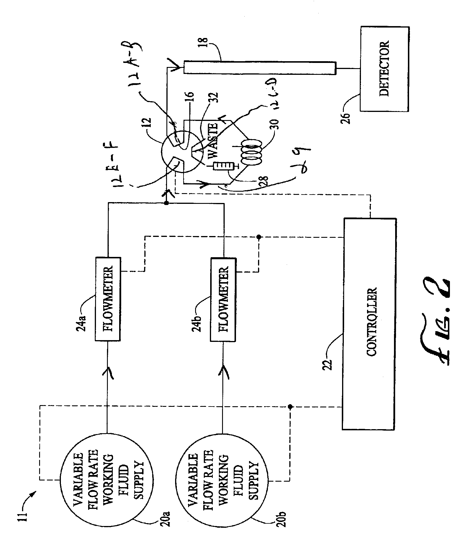
[0053]The performance of the embodiment of the invention shown in FIG. 2 has been demonstrated and the resulting test results are presented in FIG. 3. The injection valve used for this example was a Valco CN2 with a 250 nL external sample loop. The valve was pneumatically actuated under computer control. The separation column was 150 long by 0.3 mm i.d. packed with Phenomenex Luna C18 stationary phase (3 micron diameter). Detection was accomplished using a microfabricated detection cell of ˜45 nL volume and a path length of ˜4 mm. The relative standard deviation of peak height of <1% has been measured for 3 second injections conducted at 500 nL / min followed by switching to 4 μL / min for separation. A mixture of uracil, acetophenone, propiophenone and butyrophenone were run under isocratic conditions with a buffer of 55% methanol and 45% water. Exemplary chromatographic data is presented in FIG. 5, where the results from 9 separate separations are overlaid.

[0054]Although the present i...


PUM

PropertyMeasurementUnit
Lengthaaaaaaaaaa
Fractionaaaaaaaaaa
Timeaaaaaaaaaa

Abstract

A variable flow rate injector provides accurate, precise, and reproducible injection volumes that have low dispersion. The invention is particularly well-suited for HPLC injection volumes <500 nL but can be used to inject larger volumes and in different applications as well. Injections are performed at a first flow rate and separations are performed at a second flow rate. For improved HPLC system performance, the first flow rate is less than the second flow rate. The injector uses a variable flow rate fluid supply that allows rapid switching between flow rates desired for injection and flow rates desired for separations.

Description

CROSS REFERENCE TO RELATED APPLICATIONS[0001]This application is related to U.S. patent application Ser. No. 10 / 246,284, filed Sep. 17, 2002, which is a continuation-in-part of U.S. patent application Ser. No. U.S. 2002 / 01953444 filed May 24,2002, with a continuation-in-part of U.S. patent application No. U.S. 2002 / 0189947 filed Aug. 29, 2001 that claims the benefit of U.S. Provisional application No. 60 / 298,147 filed June 13, 2001. the entire disclosures of which are incorporated by reference in their entirety for any and all purposes.BACKGROUND[0002]High performance liquid chromatography (HPLC) is a technique that has been used for many years as a means of separating, identifying, purifying and quantifying components of often complex mixtures. HPLC is an important tool used by biotechnological, biomedical, and biochemical research as well as in the pharmaceutical, cosmetics, energy, food, and environmental industries.[0003]Conventional HPLC typically is performed using chromatogra...

Claims


Application Information

Patent Timeline
IPC IPC(8): G01N30/00G01N30/16G01N30/32
CPCG01N30/16Y10T436/2575G01N2030/324
Inventor NEYER, DAVID W.RAKESTRAW, DAVID J.REHM, JASON E.
Owner SCIEX
Why Eureka
Try Eureka