Hydrostatic drive and method for operating such a hydrostatic drive

a hydrostatic drive and drive shaft technology, applied in the direction of driver input parameters, gearing control, braking system, etc., can solve the problems of reduced hydrostatic drive efficiency, increased speed of allocated hydraulic motor, vehicle wheel spin, etc., to reduce the drive torque of this hydraulic motor, reduce the effect of driving power and preventing overheating and excessive wear of the operated brake devi

Inactive Publication Date: 2005-06-14
BOSCH REXROTH AG
View PDF28 Cites 34 Cited by
  • Summary
  • Abstract
  • Description
  • Claims
  • Application Information

AI Technical Summary

Benefits of technology

[0013]Whenever at least one of the brake devices is operated it is advantageous if the pivot angle of the hydraulic pump is pivoted back in order to reduce the drive power and / or the pivot angle of the hydraulic motor allocated to the operated brake device is pivoted back, in order to reduce the drive torque of this hydraulic motor. As a result overheating and excessive wear of the operated brake device are prevented.
[0014]In addition it is advantageous if the steering angle of the vehicle propelled by the drive is detected via a steering angle transmitter and if the speed difference resulting from the differential effect of two hydraulic motors for example lying opposite each other on a common vehicle axle is taken into consideration when determining the threshold value for triggering the brake device.

Problems solved by technology

If slipping occurs on one of the vehicle wheels owing to reduced surface grip the problem arises that this vehicle wheel spins and the speed of the allocated hydraulic motor increases considerably in comparison to the speed of the other hydraulic motors.
As a result the efficiency of the hydrostatic drive is substantially lower.
A disadvantage when that hydraulic motor, the vehicle wheel of which is subjected to slipping, pivots back as proposed in DE 35 43 073 C2 is however that as a result of the hydraulic motor pivoting back, although the volume flow passing through this hydraulic motor is reduced and therefore is available to the other hydraulic motors, at the same time acceleration of the associated vehicle wheel can be linked with the pivoting back of the hydraulic motor, while the pivot angle of the hydraulic pump and of the other hydraulic motors remains constant and therefore a further rise in the speed, particularly, if the rotation of the vehicle wheel is not subject to any friction related to surface grip.
This measure therefore does not exclude the risk of the pivoted back hydraulic motor overspeeding.
This patent however gives no indication of using the vehicle brake in conjunction with anti-slip regulation on a hydrostatic drive.

Method used


Image

  • Hydrostatic drive and method for operating such a hydrostatic drive
  • Hydrostatic drive and method for operating such a hydrostatic drive
  • Hydrostatic drive and method for operating such a hydrostatic drive

Examples


Embodiment Construction

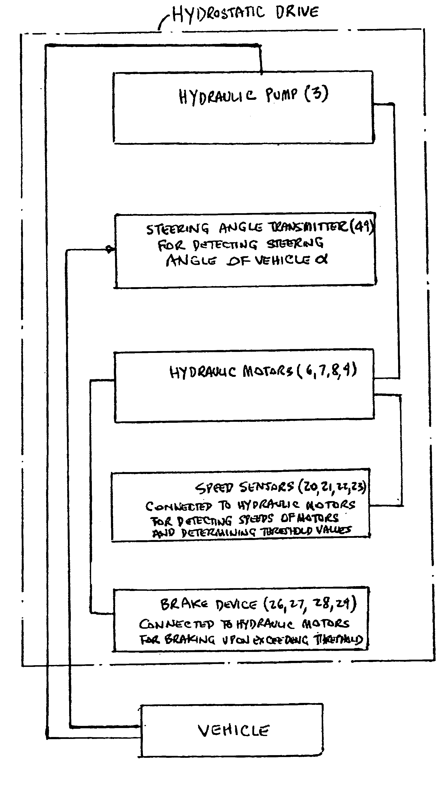
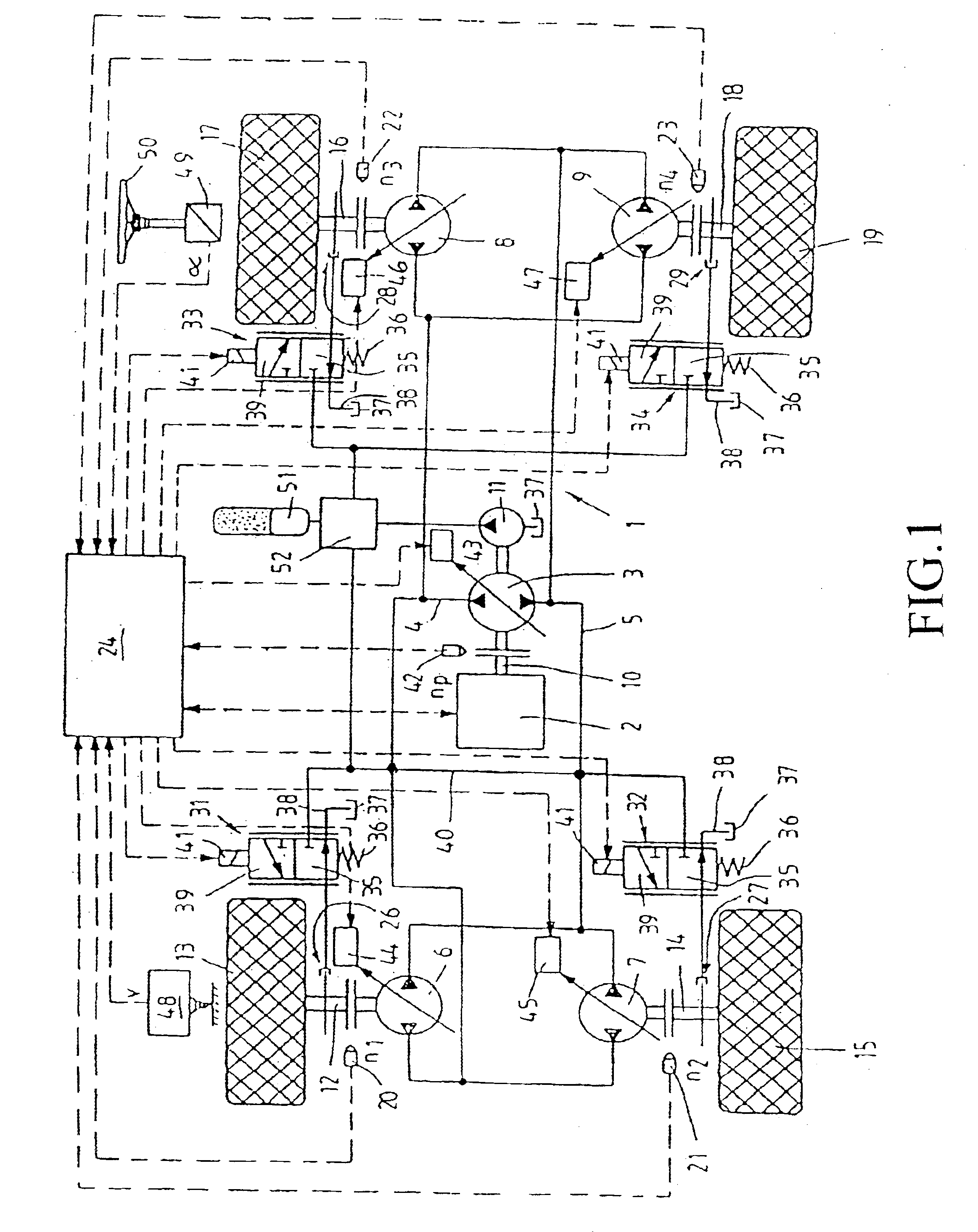
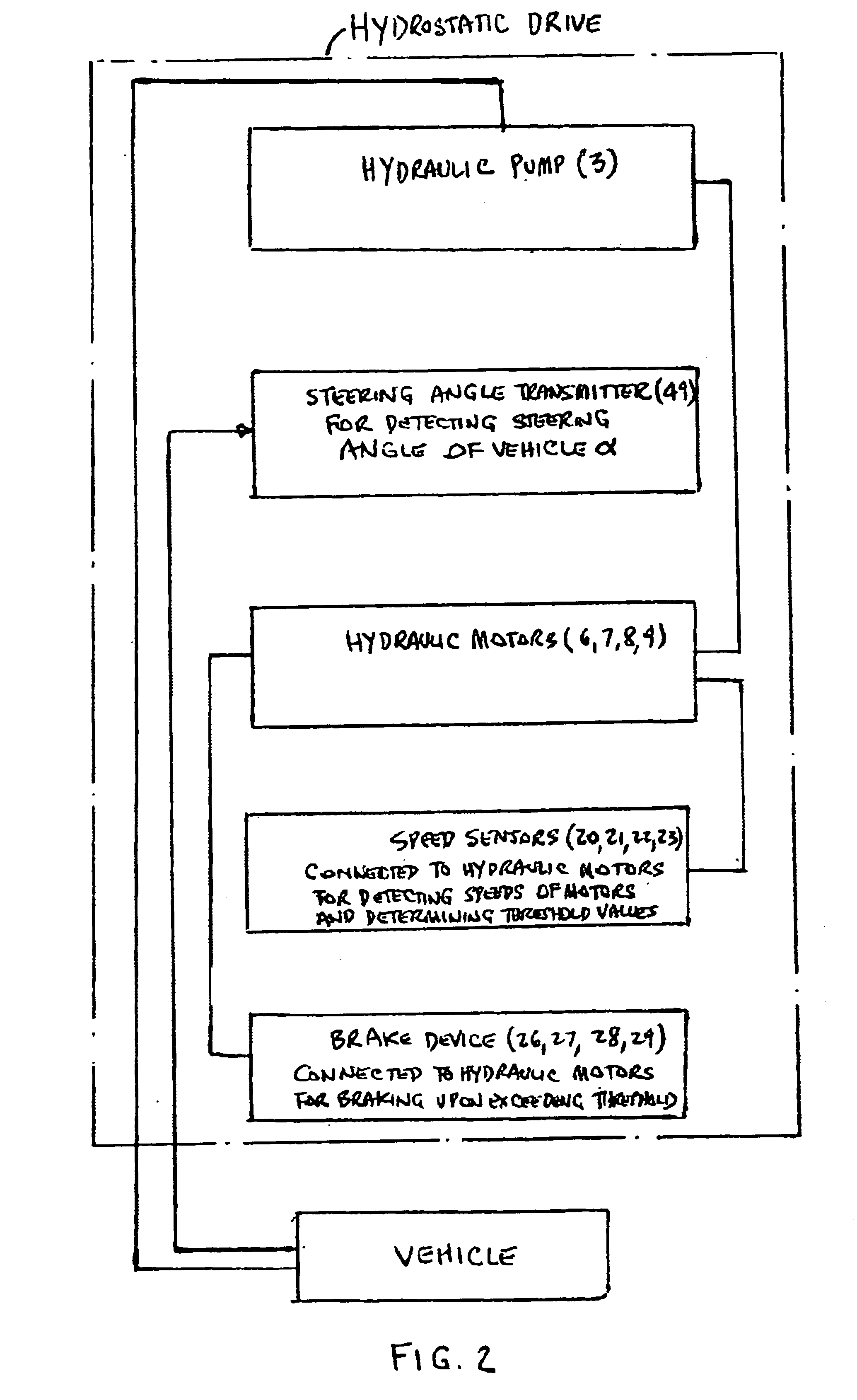
[0018]The hydrostatic drive generally designated with the reference 1 comprises a hydraulic pump 3 driven by a combustion engine 2, which is hydraulically linked via a functional circuit consisting of a first working line 4 and a second working line 5 with at least two hydraulic motors, in the embodiment with four hydraulic motors, namely the first hydraulic motor 6, the second hydraulic motor 7, the third hydraulic motor 8 and the fourth hydraulic motor 9. The hydraulic pump 3 is connected via ad rive shaft 10 to the combustion engine 2. In addition an auxiliary pump 11 sits on the drive shaft 10 in the illustrated embodiment. The hydraulic motors 6-9 are arranged parallel to each other in the functional circuit 4, 5, one of the connections of the hydraulic motors 6-9 each being linked via the first working line 4 with a connection of the hydraulic pump 3 and the other connection of the hydraulic motors 6 to 9 each is linked via the second working line 5 with the other connection o...


PUM


Abstract

A hydrostatic drive (1) with a hydraulic pump (3) and a plurality of hydraulic motors (6-9) that are hydraulically linked with the hydraulic pump (3). One speed sensor (20; 21; 22; 23) each allocated to a respective hydraulic motor (6; 7; 8; 9) and is linked with a control device (24) and detects the speed (n1; n2; n3; n4) of the allocated hydraulic motor (6; 7; 8; 9). Every hydraulic motor (6; 7; 8; 9) is functionally linked with a brake device (26; 27; 28; 29) that in turn is linked with the control device (24). When the speed (n1; n2; n3; n4) of one of the hydraulic motors (6; 7; 8; 9) exceeds a predetermined threshold value (ng), the control device (24) triggers the brake device (26; 27; 28; 29) allocated to the associated hydraulic motor (6; 7; 8; 9).

Description

BACKGROUND OF THE INVENTION[0001]1. Field of the Invention[0002]The invention relates to a hydrostatic drive with a hydraulic pump and a plurality of hydraulic motors that are hydraulically linked with said hydraulic pump as well as a method for operating such a hydrostatic drive.[0003]2. Discussion of the Prior Art[0004]A hydrostatic drive according to the present state of the technology is known from DE 35 43 073 C2. In the case of the hydrostatic drive described in this patent an adjustable hydraulic pump is driven by a combustion engine. In a functional circuit a plurality of hydraulic motors is arranged parallel to each other, which each drive different vehicle wheels. The hydraulic motors are likewise designed to be adjustable. One speed sensor which is linked with an electronic control device is allocated to each hydraulic motor or each vehicle wheel. The pivot angle of the hydraulic motors is set synchronously for all hydraulic motors.[0005]If slipping occurs on one of the v...

Claims


Application Information

Patent Timeline
Patent Type & Authority Patents(United States)
IPC IPC(8): B60K7/00B60K28/16B60K17/356B60K17/34B60T13/58B62D9/00B60T8/48B60T13/10B62D11/18B62D11/06F16H61/46F16H61/40F16H61/42B60K17/10B60W10/06B60W10/10B60W10/18B60W30/18F16H61/4157F16H61/47
CPCF16H61/47B60K17/356B60K28/16B60K28/165B60K41/267B60T8/4809B60T13/585B60W10/06B60W10/103B60W10/184B60W30/18009B62D9/002B62D11/183F16H61/4157F16H61/42F16H61/421B60K7/0015B60K2741/26B60W2520/26B60W2520/28B60K17/10B60W2540/18
Inventor RINCK, STEFANGIRSCHIKOFSKY, GUNTER
Owner BOSCH REXROTH AG
Why Eureka
Try Eureka