Truck and transmission gearshift operation device thereof

Inactive Publication Date: 2005-06-14
MITSUBISHI FUSO TRUCK AND BUS CORPORATION
View PDF9 Cites 10 Cited by
  • Summary
  • Abstract
  • Description
  • Claims
  • Application Information

AI Technical Summary

Benefits of technology

[0025]In the case of this arrangement, when impact is exerted on the cab, the column support further bend forward at its bent part, and the first connecting member buckles at the same time. As a result, the shift bracket shifts forward of the cab, which prevents part of a driver's body, for example, his or her

Problems solved by technology

Hence, the gearshift operation device disclosed in the above patent

Method used


Image

  • Truck and transmission gearshift operation device thereof
  • Truck and transmission gearshift operation device thereof
  • Truck and transmission gearshift operation device thereof

Examples


Example

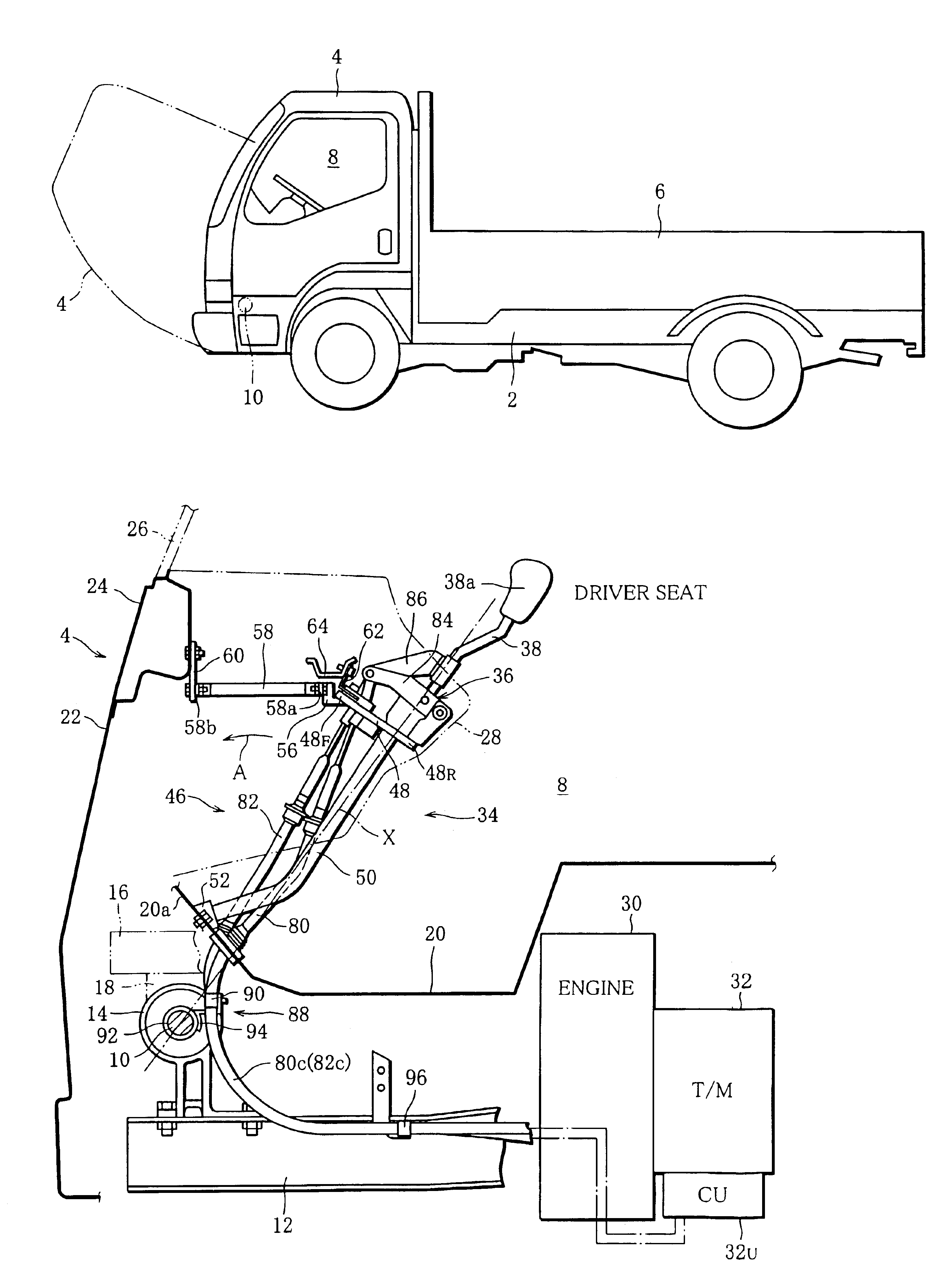
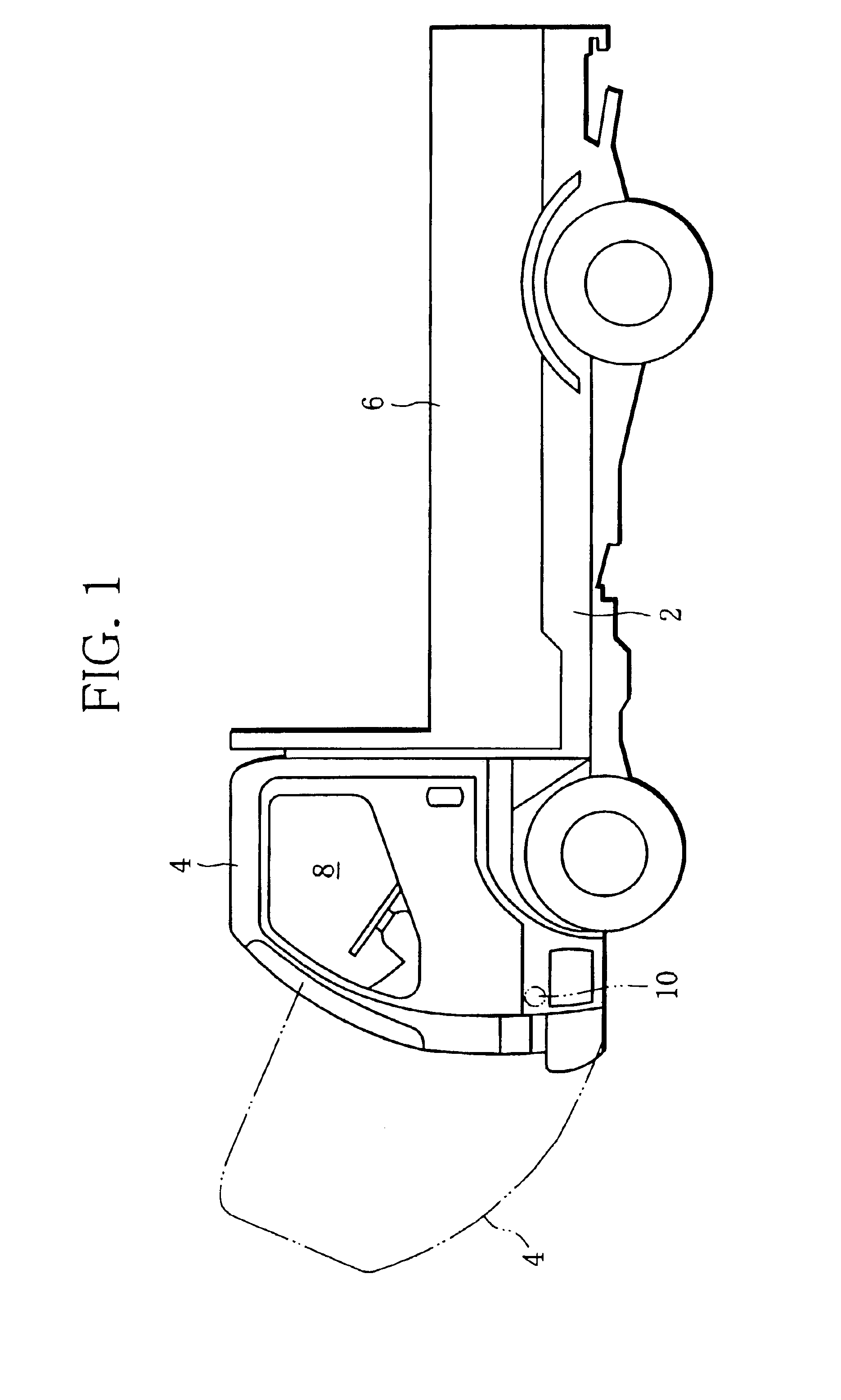
[0035]FIG. 1 shows a tiltable cab over type truck. The truck has a vehicle body 2, a cab 4 placed at a front part of the vehicle body 2, and a cargo bed 6 placed at a rear part of the vehicle body 2. The cab 4 defines a passenger compartment 8 inside, and is supported through a hinge pivot 10 fitted to the vehicle body 2. Thus, as indicated by a two-dot chain line in FIG. 1, the cab 4 can turn, or tilt upon the hinge pivot 10 forward of the truck.

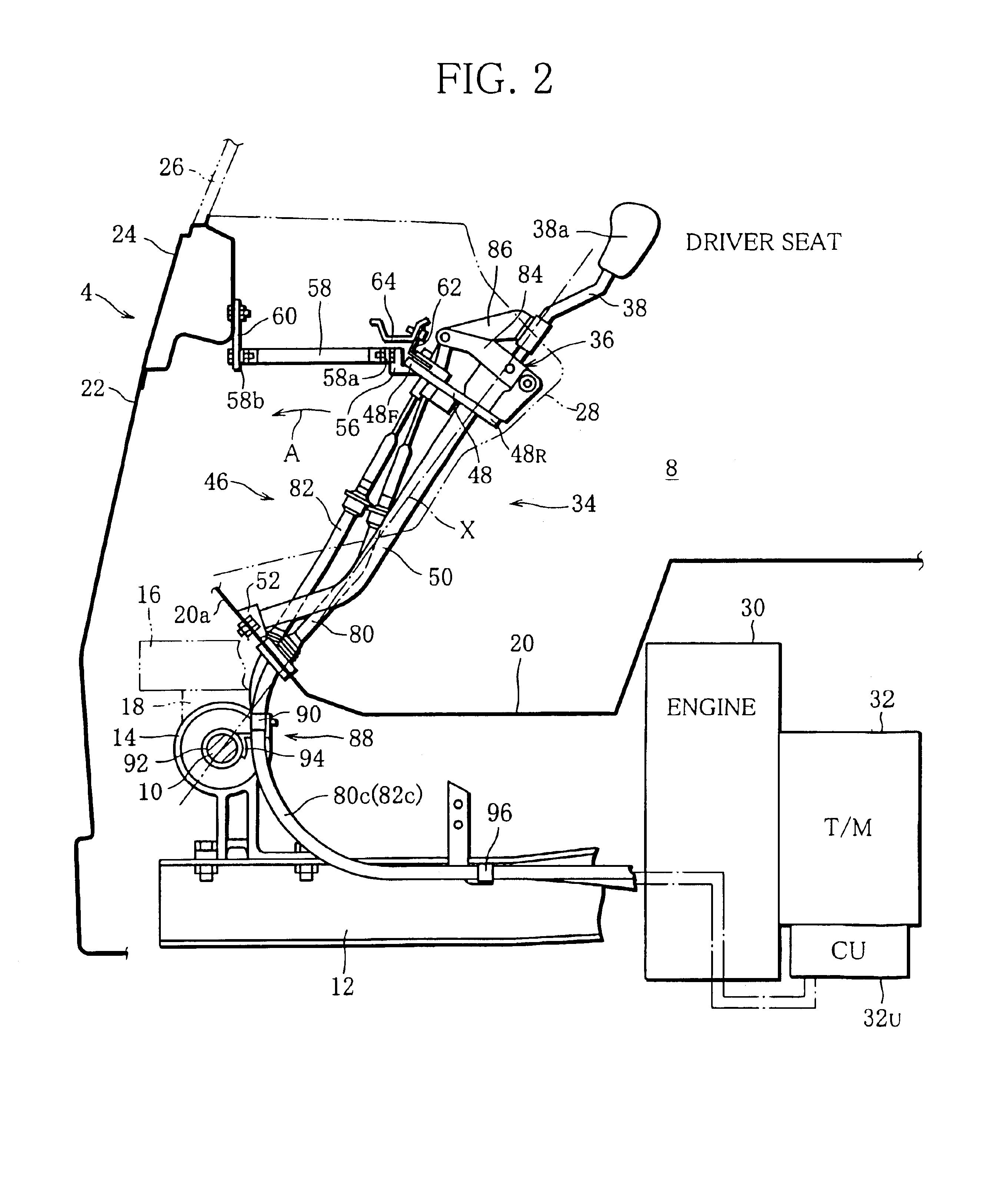
[0036]More specifically, as shown in FIG. 2, the vehicle body 2 has a pair of side rails which form a body frame. The side rails 12 are placed on the left and right sides of the vehicle body 2, and extend parallel to each other, lengthways of the vehicle body 2, namely, in the front-to-rear direction of the vehicle body 2.

[0037]A hinge bracket 14 is attached to the front end of each side rail 12. The hinge brackets 14 support the hinge pivot 10 at the opposite ends thereof.

[0038]The cab 4 has a pair of main sills 16 indicated by a two-dot c...


PUM


Abstract

A gearshift operation device for a tiltable cab over type truck comprises a shift lever placed at an instrument panel, and a select cable and a shift cable which connect an operation lever unit for the shift lever and a manual transmission. After coming out of a cab, the cables curve to pass close by a hinge pivot which supports the cab, and extend toward the manual transmission.

Description

BACKGROUND OF THE INVENTION[0001]1. Field of the Invention[0002]The invention relates to a gearshift operation device for a transmission installed in a tiltable cab over type truck.[0003]2. Description of the Related Art[0004]Generally, a passenger car has an engine room and a passenger compartment. The engine room contains an engine and a manual transmission, and the passenger compartment contains a driver seat and a shift lever for the manual transmission. The shift lever is placed near the driver seat and mechanically connected to the manual transmission through a link mechanism. With this gearshift operation device, a driver in the driver seat can shift the gear of the manual transmission by operating the shift lever manually.[0005]The gearshift operation device disclosed in Japanese Patent No. 3191626 includes a shift lever placed at an instrument panel in the passenger compartment, and the operation of the shift lever is transmitted to the manual transmission through a select ...

Claims


Application Information

Patent Timeline
IPC IPC(8): B62D33/073B62D33/06F16H61/26F16H61/36B60K20/08B60K20/02B62D27/04B62D33/067
CPCF16H61/36B62D33/073B60K20/08Y10T74/20049
Inventor MITA, MASAYOSHISUGA, TADAHARUDOHI, HIROYUKI
Owner MITSUBISHI FUSO TRUCK AND BUS CORPORATION
Why Eureka
Try Eureka