Fluid bearing and brushless motor having the same
- Summary
- Abstract
- Description
- Claims
- Application Information
AI Technical Summary
Benefits of technology
Problems solved by technology
Method used
Image

Examples
first embodiment
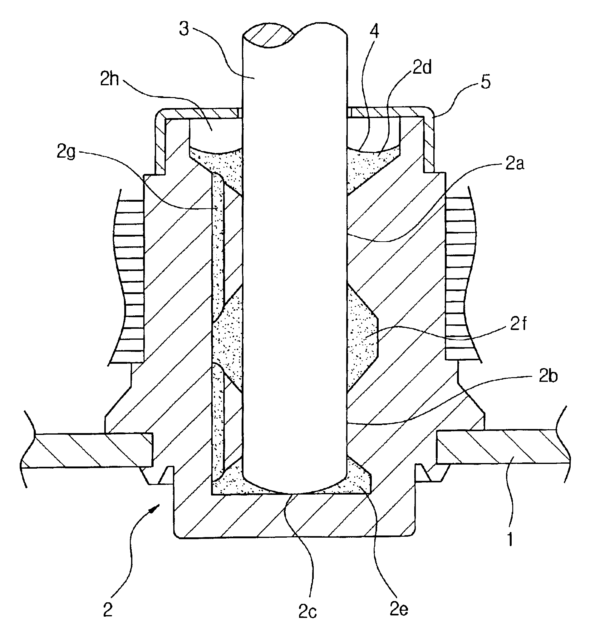
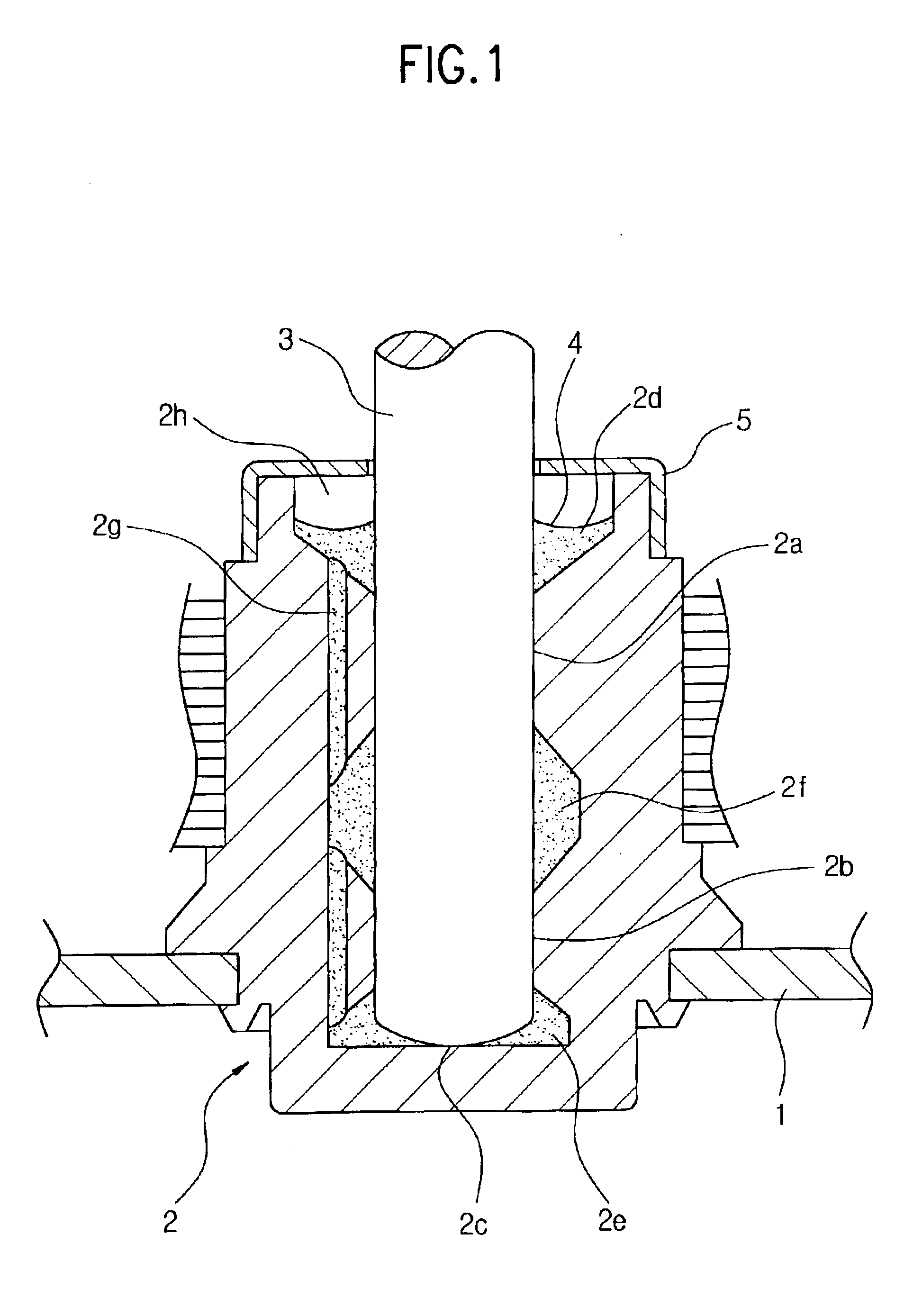
[0031]FIG. 1 is a sectional view of a kinetic pressure fluid bearing according to the present invention, in which essential parts are shown. Referring to FIG. 1, a bearing housing 2, which is fixedly mounted in a mounting hole of a stator base 1, has a cylindrical body having a blind hole therein. The bearing housing 2 also includes the upper bearing portion 2a and the lower bearing portion 2b which support the rotating shaft 3 enabling to rotate, and the thrust bearing portion 2c which axially supports a rotating shaft 3 therein.
[0032]Further, an opening oil reservoir 2d is formed at an opening portion of the bearing housing 2, and a bottom oil reservoir 2e is formed at a bottom portion of the bearing housing 2. The intermediate oil reservoir 2f is formed between an upper bearing portion 2a and a lower bearing portion 2b.
[0033]Further, the oil circulating hole 2g is formed in parallel with the rotating shaft 3 in order to communicate the opening oil reservoir 2d, the intermediate ...
second embodiment
[0054]FIG. 8 is a sectional view of a kinetic pressure fluid bearing according to the present invention, in which essential parts are shown. In FIG. 8, an upper bearing portion 22a, a lower bearing portion 22b and a thrust bearing portion 22c are formed in a bearing housing 22 fixedly assembled in a fixing hole of a stator base 1, which support a rotating shaft 3. Furthermore, an opening oil reservoir 22d is formed at an opening portion of the bearing housing 22, and a bottom oil reservoir 22e is formed at a lower portion of the bearing housing 22. An intermediate oil reservoir 22f is formed between the upper bearing portion 22a and the lower bearing portion 22b. The opening oil reservoir 22d, the lower oil reservoir 22e and the intermediate oil reservoir 22f are filled with the oil 4.
[0055]In addition, the oil circulating hole 22g is formed in the bearing housing 22 to be in parallel with the rotating shaft 3 in order to communicate the opening oil reservoir 22d with the lower oil ...
third embodiment
[0057]FIG. 9 is a sectional view of a kinetic pressure fluid bearing according to the present invention, in which essential parts are shown. In FIG. 9, an upper bearing portion 32a, a lower bearing portion 32b and a thrust receiving portion 32c are formed in the bearing housing 32 fixedly assembled in a fixing hole of a stator base 1. Also, an opening oil reservoir 32d is formed at an opening portion of a bearing housing 32, and a lower oil reservoir 32e is formed at a lower portion of the bearing housing 32. An intermediate oil reservoir 32f is formed between an upper bearing portion 32a and a lower bearing portion 32b. The opening oil reservoir 32d, the lower oil reservoir 32e and the intermediate oil reservoir 32f are filled with oil 4 such as lubricant.
[0058]Meanwhile, an oil circulating hole 32g is formed in parallel with the rotating shaft 3 in order to communicate the opening oil reservoir 32d with the intermediate oil reservoir 32f. Also, a space 32h is defined at the openin...
PUM
 Abstract
Description
Claims
Application Information
 - Generate Ideas
- Intellectual Property
- Life Sciences
- Materials
- Tech Scout
- Unparalleled Data Quality
- Higher Quality Content
- 60% Fewer Hallucinations
Browse by: Latest US Patents, China's latest patents, Technical Efficacy Thesaurus, Application Domain, Technology Topic, Popular Technical Reports.
© 2025 PatSnap. All rights reserved.Legal|Privacy policy|Modern Slavery Act Transparency Statement|Sitemap|About US| Contact US: help@patsnap.com