Impression support system for dental implants

a support system and dental implant technology, applied in the field of dental implant structure and method, can solve the problems of increasing patient discomfort, requiring increased chair time, and rarely producing accurate impressions, and achieves sufficient rigidity and enhance the accuracy of impression confirmation.

Inactive Publication Date: 2005-06-14
SUMMERS ROBERT
View PDF9 Cites 36 Cited by
  • Summary
  • Abstract
  • Description
  • Claims
  • Application Information

AI Technical Summary

Benefits of technology

[0008]In order to solve the problems in the art with dental implant impression confirmation, the present semi-rigid coping reinforcement system has been devised. The invention comprises one or more telescoping crossbrace members which are composed of a semi-rigid material such as plastic. As will be more fully described herein, the crossbraces link each coping to an adjacent coping. The ends of the telescoping crossbraces include tubular eyelets or collars which snap over each coping. A coping intermediate to others will have two separately attached c...

Problems solved by technology

There is a problem, however, because accurate impressions are rarely produced using copings to form the implant impressions.
This is a result of distortion of the impression material as the material sets.
While this solution may provide some advantages, it creates new problems of its own.
First, each wing must be individually resin bonded to another structure which requires increased chair time and discomfort to the patient.
But more importantly, the metal...

Method used


Image

  • Impression support system for dental implants
  • Impression support system for dental implants
  • Impression support system for dental implants

Examples


Embodiment Construction

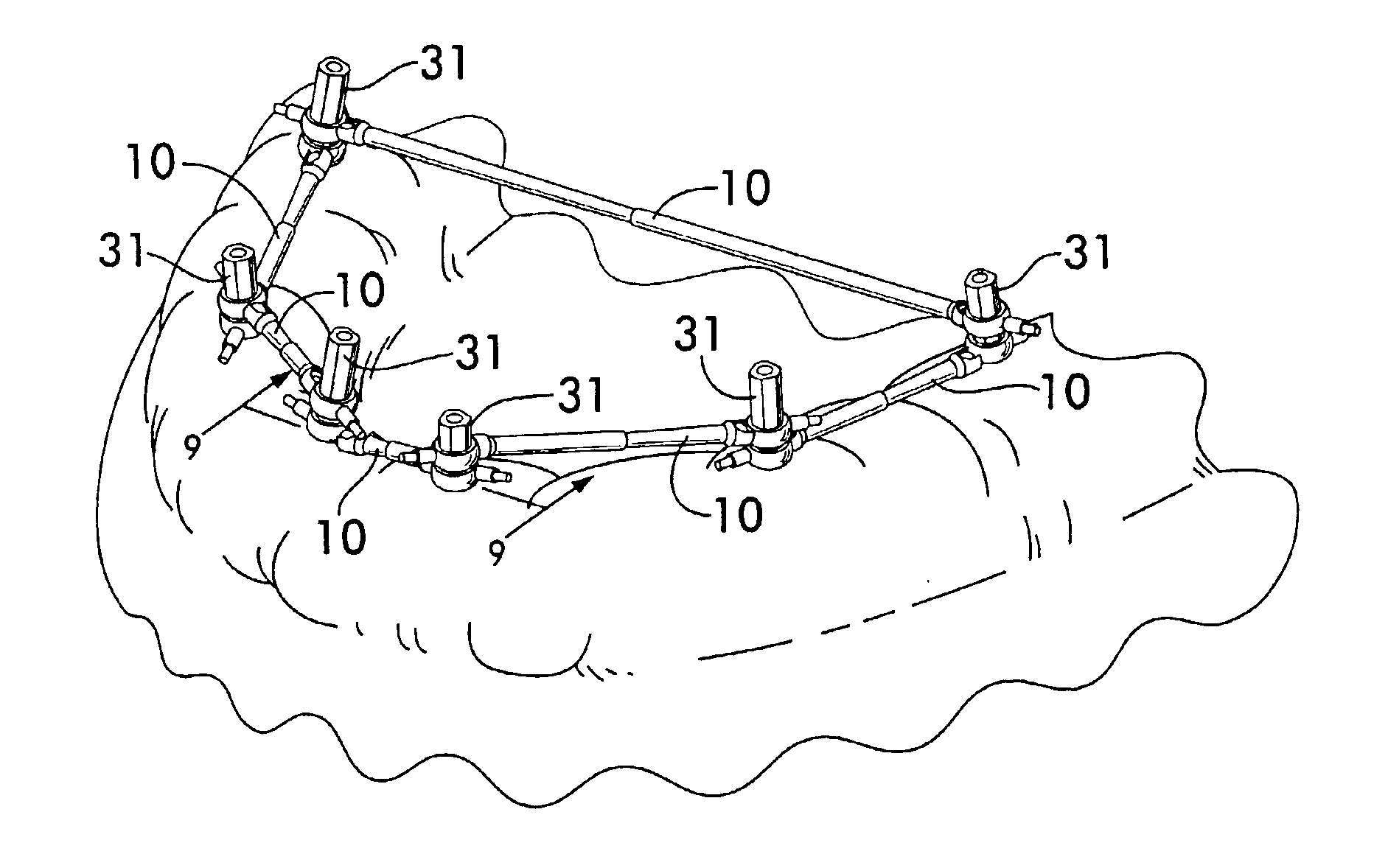
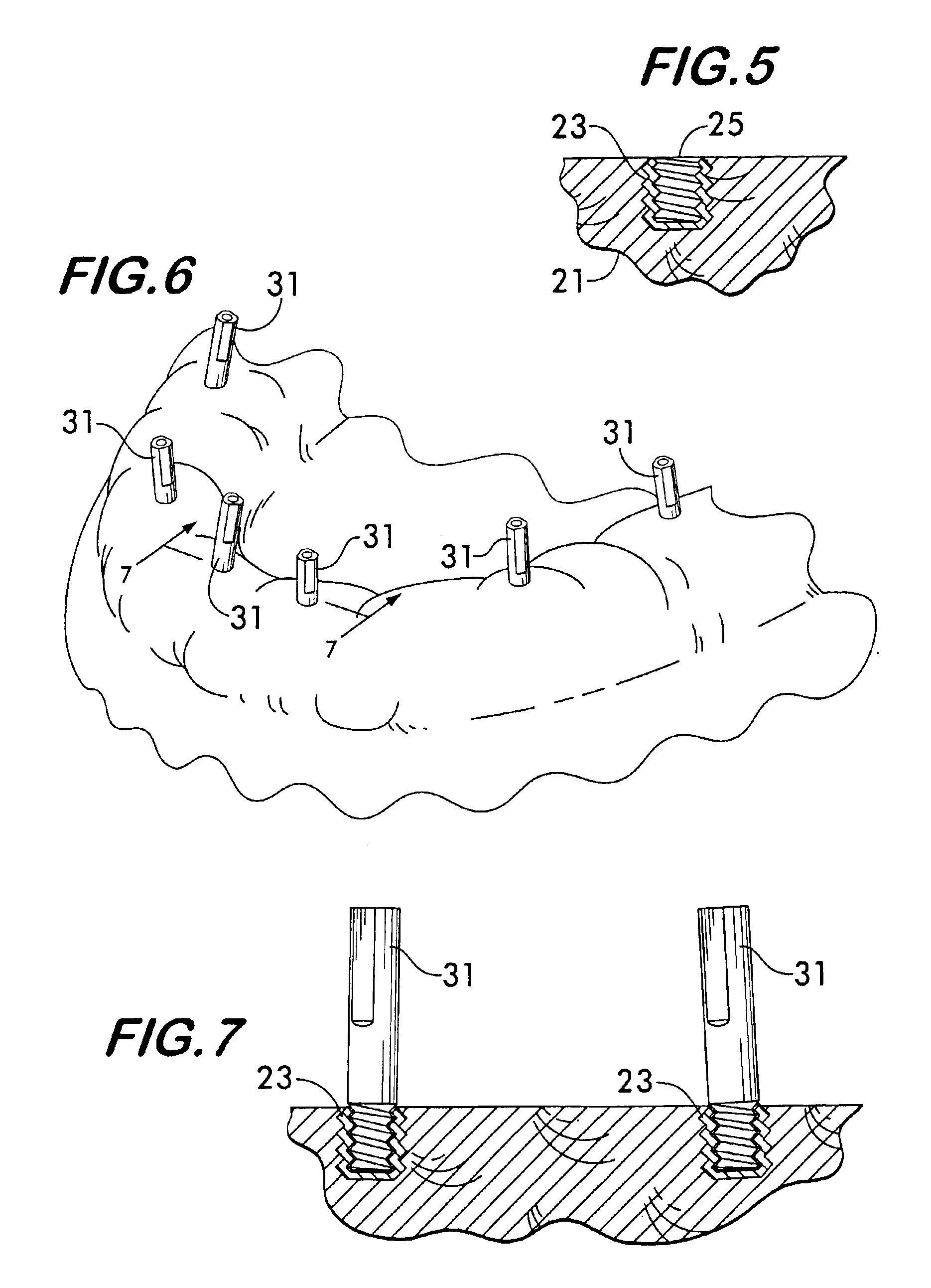
[0024]In use, the present invention generally follows the standard procedure for dental implant impression-taking so a full explanation of all details of this procedure will not be explained herein because it is well-known to those of skill in the art. The sequence of figures that will now be described embody the steps of dental implant coping impression-taking utilizing the reinforcement system of the invention.

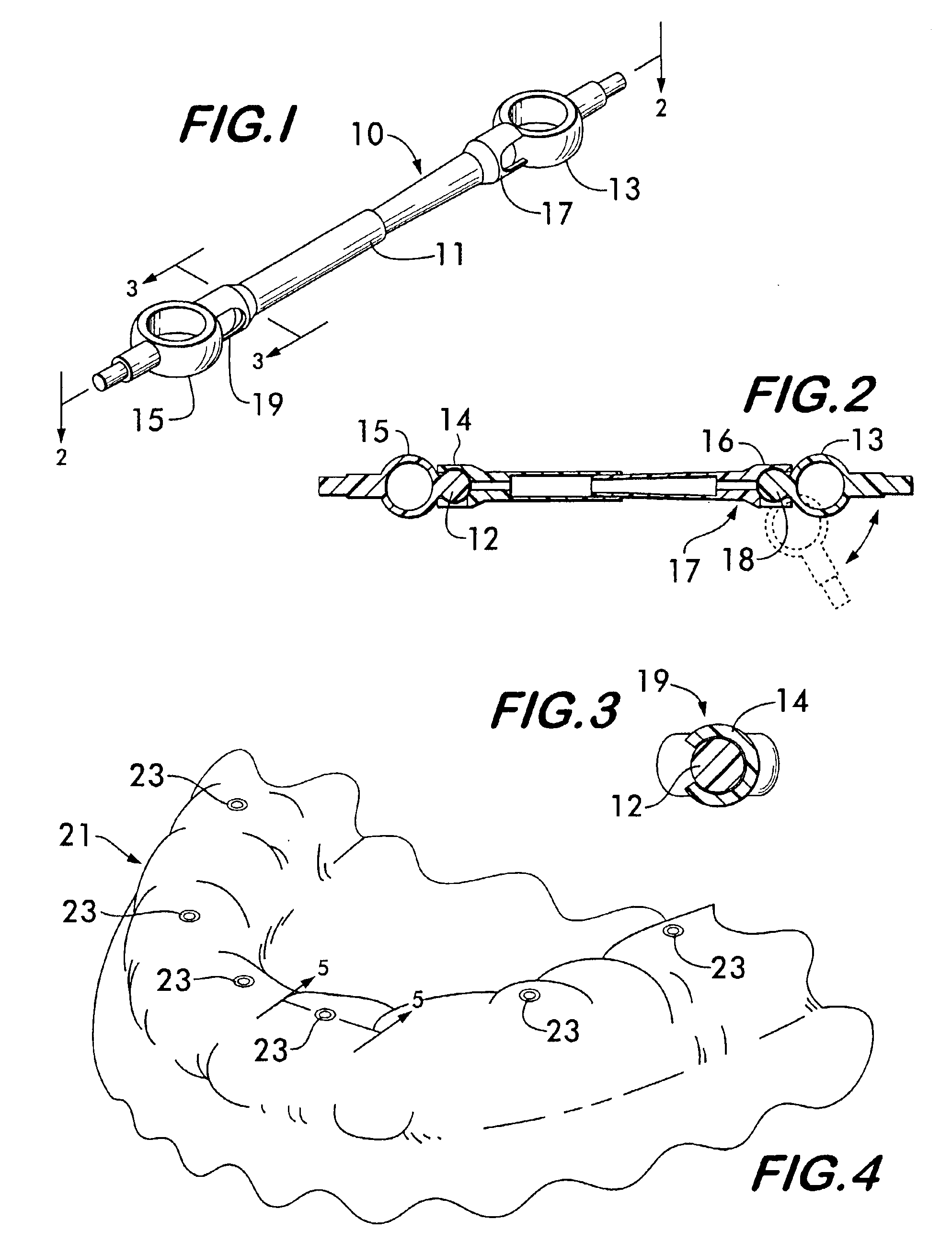
[0025]Referring now to FIG. 1, a coping crossbrace 10 of the present invention is depicted. Each crossbrace includes a telescoping body member 11 with articulated collars 13 and 15 at opposite ends. Each collar is attached to the main body portion by articulated joints 17 and 19 which in this case are slotted ball-and-socket type joints. As shown in FIG. 2 and as will be readily understood, the various joints of the crossbrace permit the collars to be displaced angularly and linearly with respect to each other to accommodate non-parallel copings. Each articulated joint inclu...


PUM


Abstract

A dental implant impression confirmation system utilizes one or more telescoping crossbrace members. Each crossbrace links one coping to an adjacent coping. The ends of the telescoping crossbraces include tubular eyelets or collars which each attach to a coping by snap-fit. The crossbraces further include articulated joints at each end to accommodate attachment between copings which are not parallel. The crossbrace members are preferably composed of a semi-rigid material such as plastic which permits resilience of the confirmation system to allow for the withdrawal of the copings from the implants while supplying sufficient rigidity to enhance the accuracy of the impression.

Description

FIELD OF THE INVENTION[0001]The present invention relates to structures and methods for forming impressions of dental implants. More specifically, it relates to structures for providing support to the impression material used when taking dental implant impressions to obtain a more accurate model of a patient's mouth and the dental implant components.BACKGROUND OF THE INVENTION[0002]Dental implants are well known in the dental arts as a means for providing a prosthetic tooth or teeth as an alternative to a fixed bridge or removable dentures. The dental implant procedure begins with first surgically exposing the jaw bone and then drilling the surface of the bone where the prosthetic tooth is to be attached and then inserting an implant. A flap of skin is then sewn over the site and during a healing period that follows, the bone becomes biologically attached to the surface of the implant. Later, after the implant has become thoroughly attached to the bone, the flap is removed. Next, an...

Claims


Application Information

Patent Timeline
IPC IPC(8): A61C8/00
CPCA61C8/0048A61C8/0001
Inventor SUMMERS, ROBERT
Owner SUMMERS ROBERT
Why Eureka
Try Eureka