
Laparoscopic insertion device

Inactive Publication Date: 2005-06-14
NORTHGATE TECH
View PDF44 Cites 63 Cited by
  • Summary
  • Abstract
  • Description
  • Claims
  • Application Information

AI Technical Summary

Benefits of technology

[0013]Each aspect of the present invention provides the advantage of improving fluid flow in an insertion device during a laparascopic procedure.
[0014]Each of the first two aspects of the present invention provides the advantage of decreasing the cost of laparoscopic procedures by using a single insertion device for simultaneously conveying multiple fluids during a laparascopic procedure.
[0015]Each of the first two aspects of the present invention provides the advantage of decreasing the complexity of laparoscopic procedures by simultaneously conveying multiple fluids during a laparascopic procedure.
[0016]Each of the first two aspects of the present invention provides the advantage of reducing the risk of contamination of an insertion device by multiple fluids conveyed by the insertion device during a laparoscopic procedure.

Problems solved by technology

One disadvantage of the inserting the medical instrument into the Verres needle is that the medical instrument causes a significant restriction to the flow of insulating gas within the Verres needle since the medical instrument and the insufflating gas share a common passage or channel in the inner cannula.
Such restriction in flow of the insufflating gas can limit the effectiveness of the insufflator.
Like the Verres needle described previously, inserting the medical instrument into the cannula causes a significant restriction to the flow of insufflating gas within the trocar due to the sharing of a common passage by the medical instrument and the insufflating gas.
Another disadvantage of insertion devices, such as Verres needles and trocars, is that only one fluid can be conveyed within the insertion device at any one time.
Using multiple insertion devices lead to the disadvantages of increasing the cost of the procedure, the complexity of the procedure and potentially increasing trauma incurred by the patient.
Such a mode of operation could lead to contamination of the Verres needle or trocar with multiple fluids, increase the complexity of timing the application of fluids and requiring special metering and / or control devices.

Method used


Image

  • Laparoscopic insertion device
  • Laparoscopic insertion device
  • Laparoscopic insertion device

Examples


Embodiment Construction

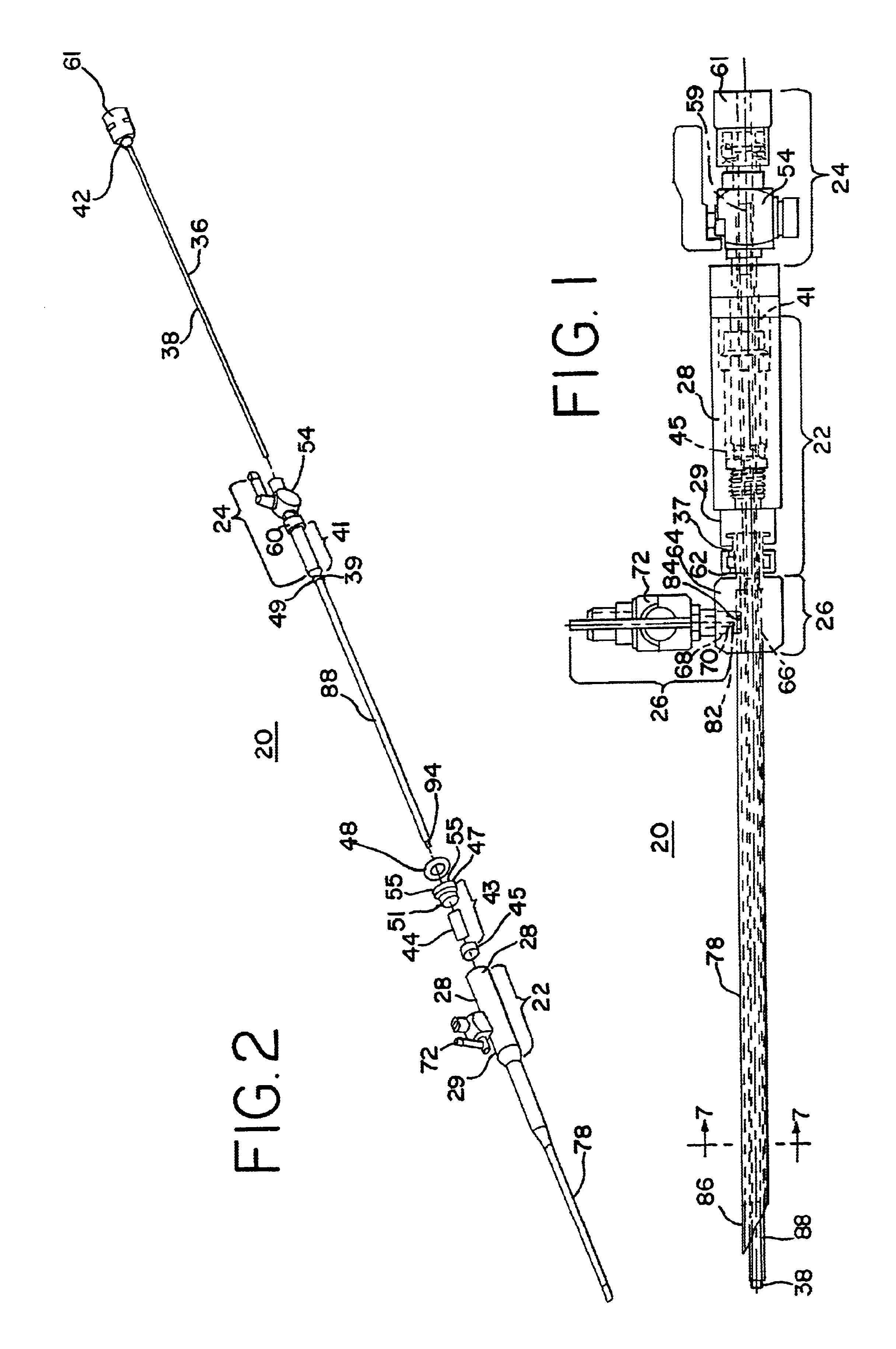
[0038]Referring now to FIGS. 1-7, an insertion device, such as Verres needle 20, includes a lumen housing sub-assembly 22, a first fluid port section 24 and a second fluid port section 26.

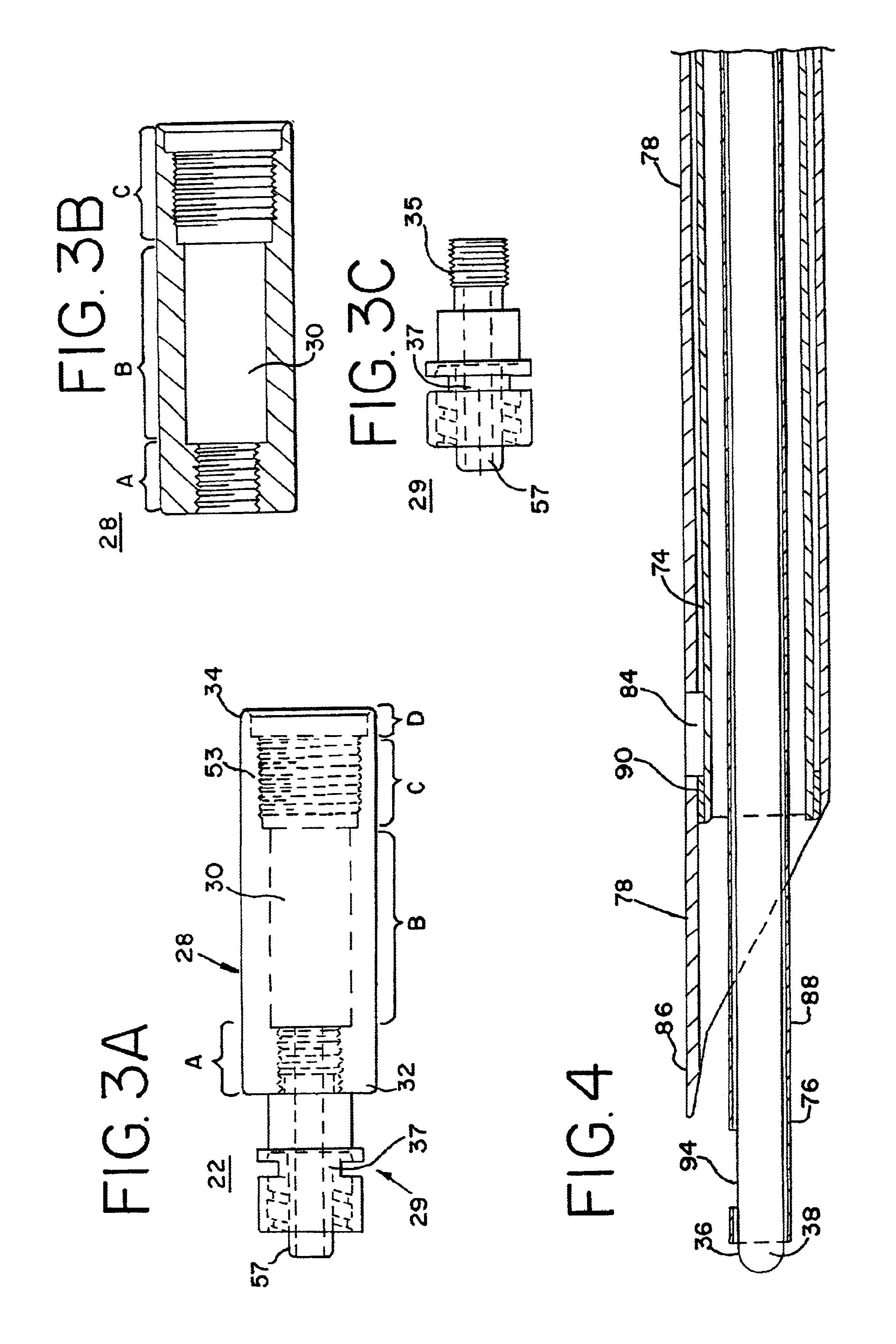
[0039]As shown in FIGS. 1, 2, 3A-B and 5, the lumen housing sub-assembly 22 includes a cylindrical-like lumen housing 28 that is threadedly attached to a lumen housing adapter 29. As shown in FIGS. 3A-B, the lumen housing 28 includes a central channel 30 that extends from a distal end 32 to a proximal end 34 of the lumen housing 28. The central channel 30 has a length of approximately 1.437 inches. The channel 30 has a diameter that varies in a step-like manner. For example, the channel 30 has four distinct portions: 1) a distal portion A that has a diameter of approximately 0.36 inches and a length of approximately 0.312 inches, 2) an intermediate distal portion B that has a diameter of approximately 0.302 inches and a length of approximately 0.725 inches, an intermediate proximate portion C that ...


PUM


Abstract

A method of treatment of a body cavity of an animal that includes inserting a portion of an insertion device into a body cavity of an animal and simultaneously supplying from the inserted insertion device a first fluid and either a medical instrument or a second fluid into the body cavity, wherein the first fluid and either the medical instrument or the second fluid are not in fluid communication with one another within the insertion device.

Description

BACKGROUND OF THE INVENTION[0001]1. Field of the Invention[0002]The present invention relates generally to instruments for laparoscopic surgery. In particular, it relates to an improved laparoscopic surgical instrument that can simultaneously perform multiple tasks and procedures independent of one another.[0003]2. Discussion of Related Art[0004]Laparoscopic surgery involves the use of small incisions to insert surgical instruments of 3-10 millimeter (mm) diameter into the abdominal cavity. In performing such surgery, telescopes of 5-11 mm diameter usually also are inserted through the abdominal wall in order to view intraabdominal contents during the surgery. The initial step in laparoscopic surgery is to insert a needle of about 2 mm diameter through the abdominal wall such that the tip of the needle lies in the abdominal cavity itself. About 2-4 liters of a medical grade sterilized gas such as carbon dioxide, is insufflated through the needle and into the cavity. This procedure s...

Claims


Application Information

Patent Timeline
IPC IPC(8): A61B17/34
CPCA61B17/3496A61B17/3474A61B2017/3447
Inventor MANTELL, ROBERT R.MANZIE, PETER A.
Owner NORTHGATE TECH
Learn More