

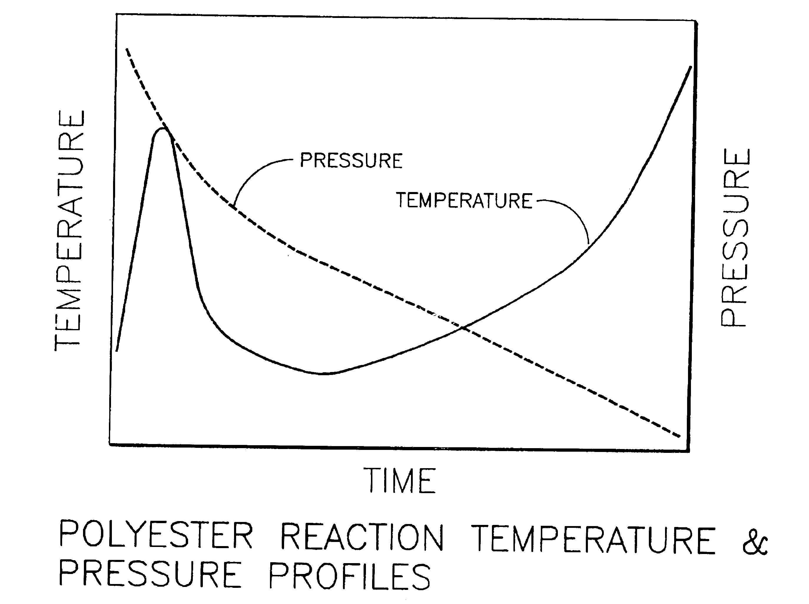
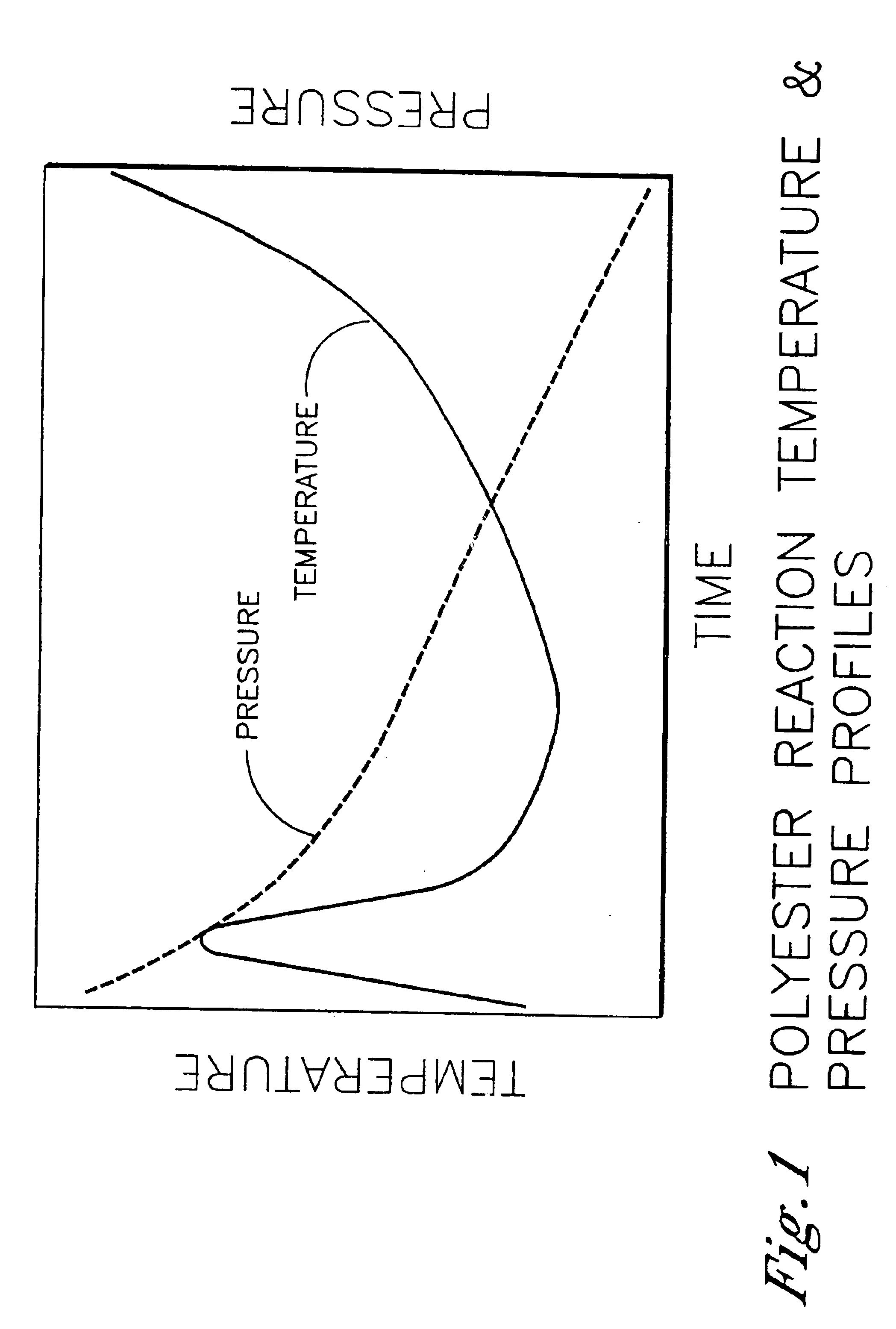
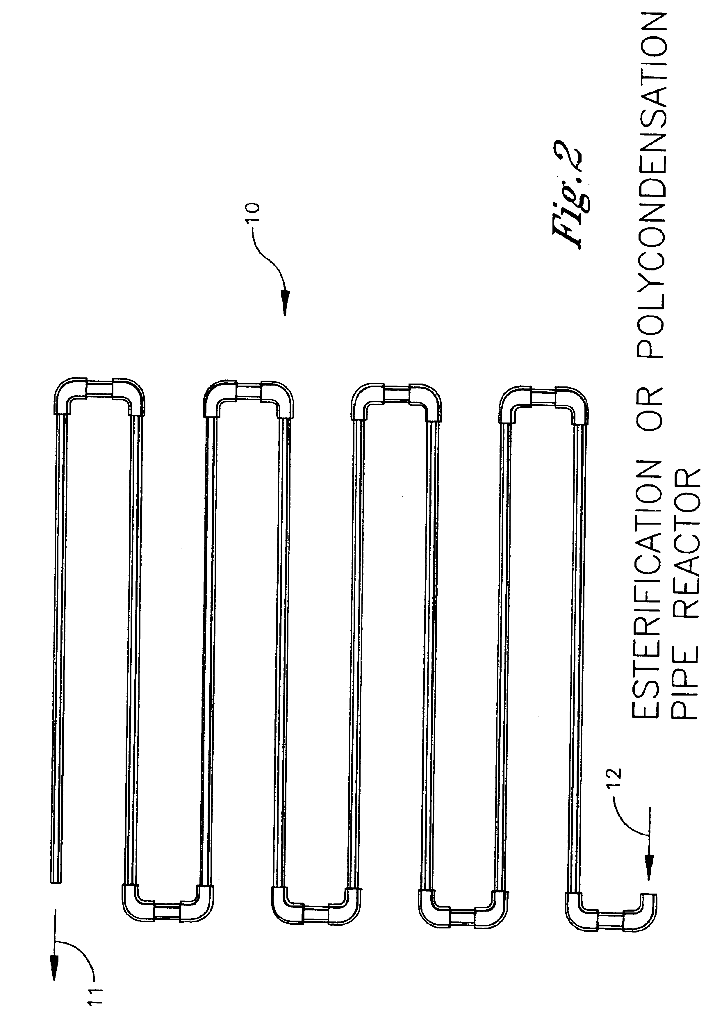
Polyester process using a pipe reactor
a technology of polyethylene and pipe reactor, which is applied in the direction of auxillary shaping apparatus, chemical/physical/physical-chemical stationary reactor, auxillary shaping apparatus, etc., can solve the problems of affecting the flow rate of fluids, too many heating coils, and insufficient space between coils
- Summary
- Abstract
- Description
- Claims
- Application Information
AI Technical Summary
Benefits of technology
Problems solved by technology
Method used
Image

Examples
example 1
[0516]Using ASPEN modeling, exemplary pipe lengths and heat exchange areas were calculated for a pipe reactor system for each of PET and PETG. The results are shown in Table 1 below.
[0517]
TABLE 1EsterificationPolycondensationPipe Diameterin 1412 14 16PET Plant Pipeft73317751905LengthStage 1Stage 2PET Plant Heatft22200 2000Exchanger AreaPETG Plant Pipeft 7975 255 680LengthStage 1Stage 2Stage 3PETG Plant Heatft22200 1900Exchanger Area
example 2
[0518]The liquid volume required for a polyester pipe reactor design is substantially less than a conventional polyester process. For example, ASPEN modeling was run to compare to a 300 million pounds per year PET bottle plant. The results are set forth in Table 2 below.
[0519]
TABLE 2EsterificationStandard Plant 100 m3Pipe Reactor 8.4 m3% Reduction92%PolycondensationStandard Plant 35.6 m3Pipe Reactor 14.2 m3% Reduction60%Total PlantStandard135.6 m3Pipe Reactor 22.6 m3% Reduction83%
examples 3-7
[0520]Various ASPEN modeling was run to determine operating conditions and performance results for various polyesters of the invention. The modeling was based upon an apparatus of the invention of either FIG. 17a or 17b as noted in the Tables below. The inherent viscosity (I.V.) is measured by dissolving of 0.25 g of polymer in 50 mL in the solvent, which consists of 60% phenol and 40% 1,1,2,2-tetracholorethane by weight. The measurement is made at 25 deg C. using either a Viscotek Differential or Modified Differential Viscometer using ASTM D 5225, “Standard Test Method for Making Solution Viscosity of Polymers with a Different Viscometer.” The results for Examples 3-7 are set forth below in Tables 3-7, respectively.
[0521]
TABLE 3HOMO PET - Bottle PolymerRecycle Rate5 parts monomer to1 part PTA by weightProduction Rate300 millionpounds / yearEG to PTA feed mole1.6ratioPolycondensation zonePolycondensation zonePolycondensation zoneReactor (See FIG. 17A)Esterification123Temperature (C.)2...
PUM
| Property | Measurement | Unit |
|---|---|---|
| angle | aaaaa | aaaaa |
| angle | aaaaa | aaaaa |
| angle | aaaaa | aaaaa |
Abstract
Description
Claims
Application Information