Injection-seeding of a multi-tone photonic oscillator

a multi-tone, lightwave oscillator technology, applied in the field of injection seeding of multi-tone rf lightwave oscillators, can solve the problems of bulky and expensive set of low phase noise rf synthesizers

Inactive Publication Date: 2005-06-14
HRL LAB
View PDF11 Cites 64 Cited by
  • Summary
  • Abstract
  • Description
  • Claims
  • Application Information

AI Technical Summary

Benefits of technology

[0010]The present invention includes a modulator, an optical feedback loop, and a photodetector similar to the prior art. However, the present invention is different in that electrical injecti...

Problems solved by technology

Previous means for generating such low phase noise multitone carriers with controllable frequency ...

Method used


Image

  • Injection-seeding of a multi-tone photonic oscillator
  • Injection-seeding of a multi-tone photonic oscillator
  • Injection-seeding of a multi-tone photonic oscillator

Examples


Embodiment Construction

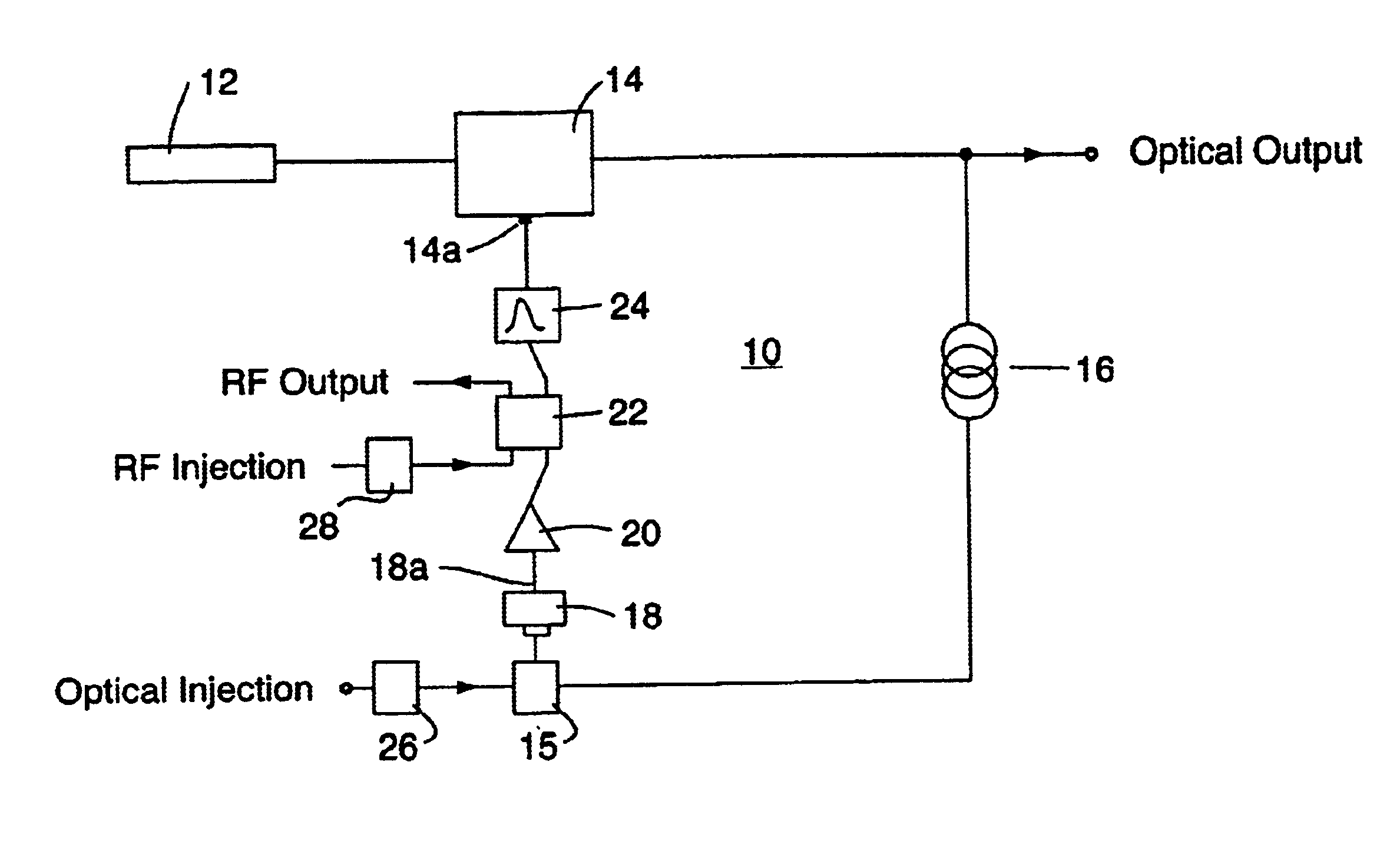
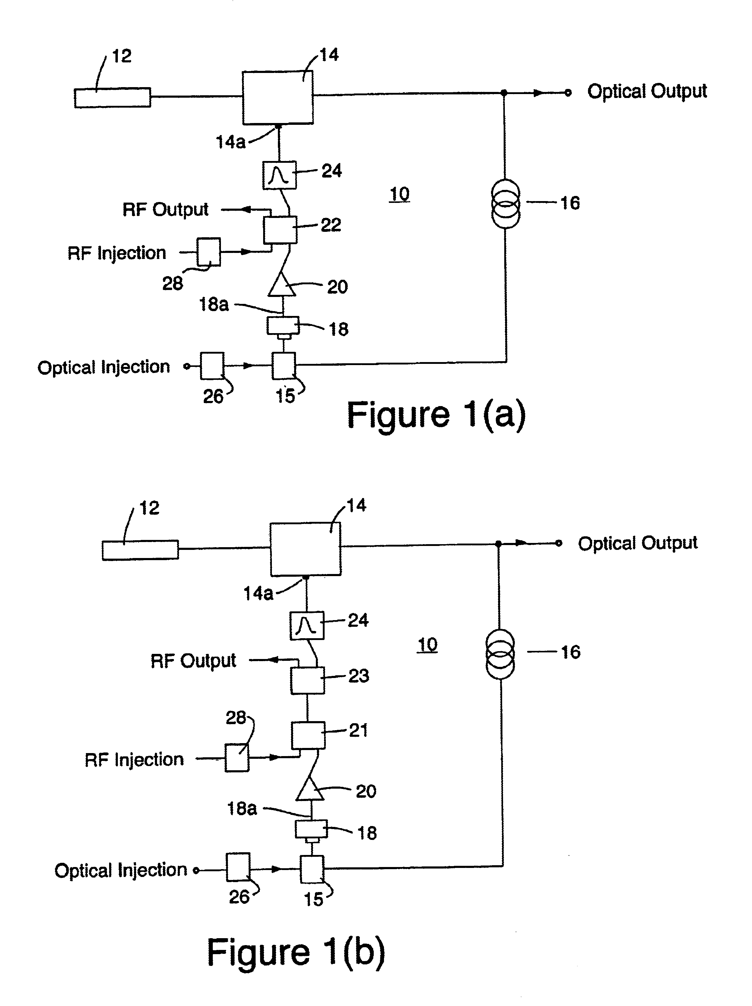
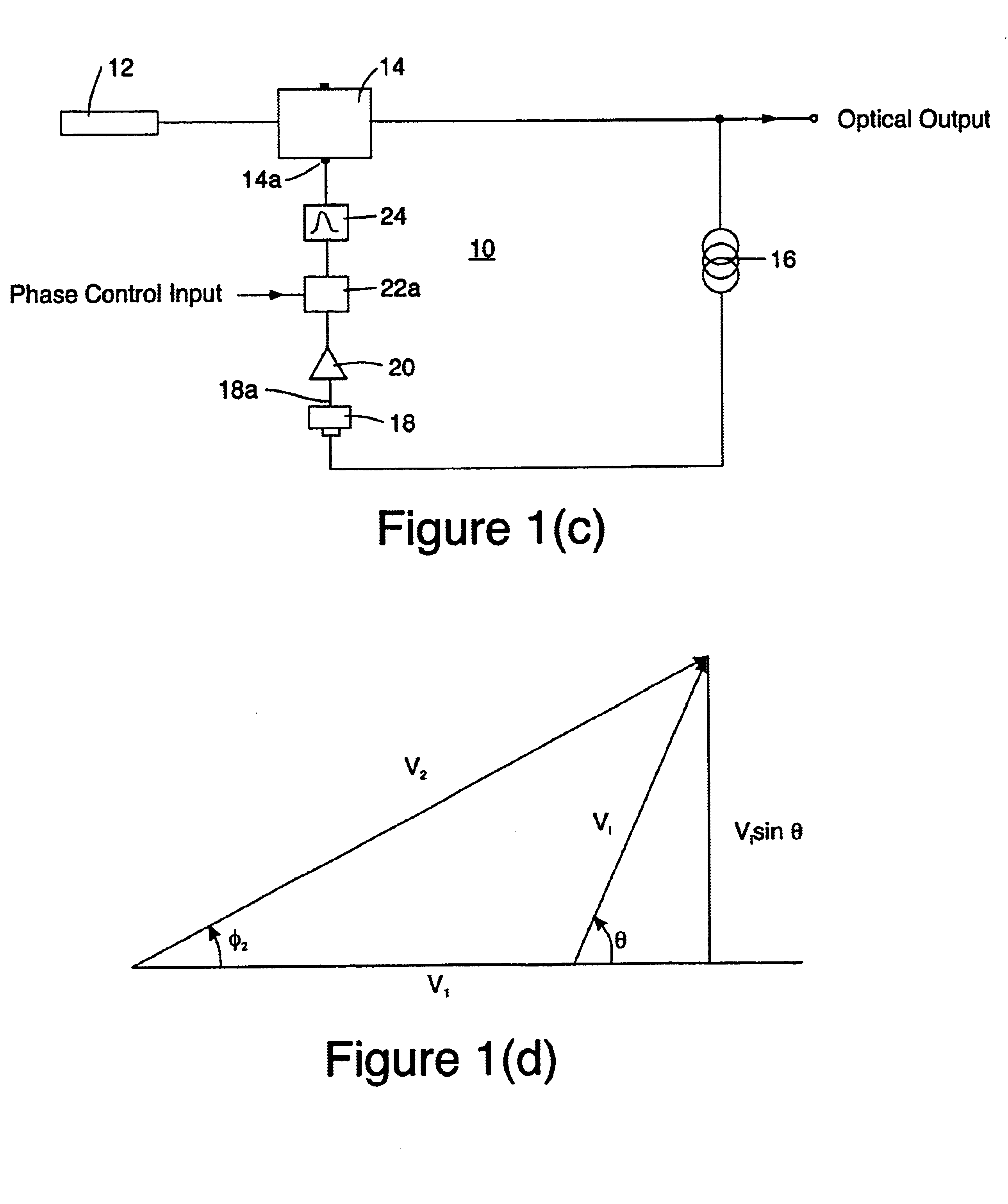
[0024]A detailed block diagram of the multi-tone photonic oscillator 10 is shown in FIG. 1(a) which includes a laser 12, an optical modulator 14 and a feedback loop. The feedback loop includes a lightwave delay path 16, a photodetector 18, a low-noise electrical amplifier (LNA) 20, a coupler 22 or a coupler 15 and a RF bandpass filter 24. The laser light, which supplies the power for the oscillator, is modulated by the RF signal at the electrical input 14a of the optical modulator 14. The modulated lightwave is sensed by the photodetector 18, whose electrical output 18a is fed back to the modulator 14 following amplification by LNA 20 and bandpass filtering by filter 24. The bandpass filter 24 sets the bandwidth of the generated RF multitone comb spectrum.

[0025]The operating principal of the multi-tone oscillator is as follows. Random noise generated in the feedback loop modulates the laser light, which after propagating through the optical delay path 16 and being photodected by det...


PUM


Abstract

A multi-tone photonic oscillator comprises a laser; an optical modulator coupled to the laser; and a delay line and a photodetector coupled to the optical modulator for generating a delayed electrical signal representation of the output of the optical modulator; wherein the optical modulator being responsible for the delayed electrical signal for generating multiple tones where the frequency intervals of the tones is a function of the amount of delay imposed by the delay line.

Description

CROSS REFERENCE TO RELATED APPLICATIONS[0001]This application claims the benefit of U.S. provisional application No. 60 / 332,371 filed Nov. 15, 2001 for an “Injection-seeding of a Multi-tone Photonic Oscillator” by Daniel Yap and Keyvan Sayyah, the disclosure of which is hereby incorporated herein by reference.[0002]This application is related to a patent application entitled “Agile RF-Lightwave Waveform Synthesis and an Optical Multi-Tone Amplitude Modulator” bearing serial No. 60 / 332,367 and filed Nov. 15, 2001, and its corresponding non-provisional application bearing Ser. No. 10 / 116,801 and filed on the same date as the present application, the disclosures of which are hereby incorporated herein by this reference. These related applications are owned by the assignee of this present application.[0003]This application is related to a provisional patent application entitled “Agile Spread Waveform Generator” bearing serial No. 60 / 332,372 and filed Nov. 15, 2001, and its corresponding...

Claims


Application Information

Patent Timeline
IPC IPC(8): G01J1/34G01J5/08G01J1/10H01S3/10H04B1/04
CPCH04B1/0475
Inventor SAYYAH, KEYVANYAP, DANIEL
Owner HRL LAB
Why Eureka
Try Eureka