Unlock instant, AI-driven research and patent intelligence for your innovation.

End-of-life protection for compact fluorescent lamps

a fluorescent lamp and end-of-life protection technology, which is applied in the field of fluorescent lamps, can solve the problems of compact fluorescent lamps experiencing end-of-life failure, discharging considerable power, and plastic housing of ballast to melt, and achieve the effect of low thermal conductivity

Inactive Publication Date: 2005-06-14
LEDVANCE LLC
View PDF6 Cites 5 Cited by
  • Summary
  • Abstract
  • Description
  • Claims
  • Application Information

AI Technical Summary

Benefits of technology

[0007]It is yet another object of the invention to improve the safety of compact fluorescent lamps.
[0010]The safe end-of-life device has a low thermal conductivity and provides thermal insulation between the glass lamp envelope and the plastic top surface of the housing. Now, at end-of-life, the glass tube will overheat causing a crack to develop in the glass, which will vent the lamp and extinguish it before any damage to the plastic housing can occur.

Problems solved by technology

Unlike the incandescent lamps they replace, which cease operation immediately upon failure of the filament, compact fluorescent lamps experience end-of-life failure when the filaments of the lamp have depleted their emissive material.
Under these conditions the electronic ballast can continue to operate the lamp and dissipate considerable power.
This power dissipation can cause localized heating of the glass lamp envelope in the vicinity of the cathode, causing the plastic housing of the ballast to melt.
Increasing the space between the lamp envelope and the wall of the ballast housing is not practical since safety standards for self-ballasted compact fluorescent lamps limit the amount of space between the glass lamp tube and the plastic housing to minimize electrical shock hazards.

Method used


Image

  • End-of-life protection for compact fluorescent lamps
  • End-of-life protection for compact fluorescent lamps

Examples


Embodiment Construction

[0012]For a better understanding of the present invention, together with other and further objects, advantages and capabilities thereof, reference is made to the following disclosure and appended claims in conjunction with the above-described drawings.

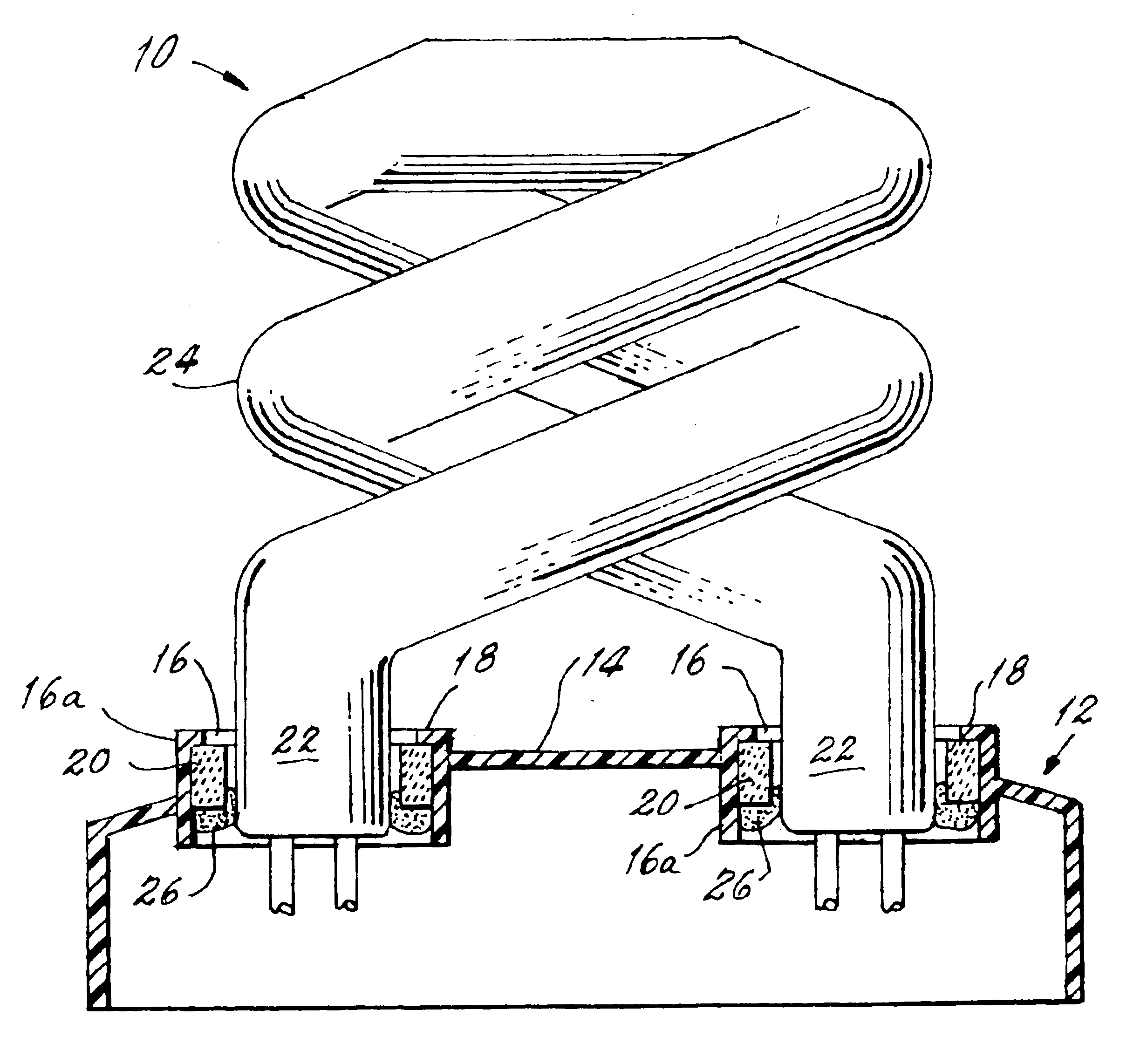
[0013]Referring now to the drawings with greater particularity, there is shown in the FIGURE a self-ballasted fluorescent lamp 10 that comprises a housing 12 formed to contain a ballast (not shown). The housing 12 has a top surface 14 with an opening 16 leading from the exterior of the housing 12 to the interior. In the FIGURE, two openings 16 are shown to receive the two ends 22 of a spiral lamp 24. The openings 16 can be in the form of raised bosses having upstanding walls 16a. A restricted portion 18, which can take the form of a flange, is formed with the opening 16 and a safe end-of-life enabling device 20 is positioned in the opening 16 and in contact with the restricted portion 18. The safe end-of-life device 20 is tubular, has ...


PUM


Abstract

A self-ballasted fluorescent lamp (10) that comprises a housing (12) formed to contain a ballast. The housing (12) has a top surface (14) with openings (16) leading from the exterior of the housing (12) to the interior. The openings (16) can be in the form of raised bosses having upstanding walls (16a). A restricted portion (18), which can take the form of a flange, is formed with the opening (16) and a safe end-of-life enabling device (20) is positioned in the opening (16) and in contact with the restricted portion (18). The safe end-of-life device (20) is tubular, has low thermal conductivity and in preferred forms of the invention is a glass such as quartz or a ceramic such as aluminum oxide. The ends (22) of a fluorescent lamp (24) penetrate the tubular end-of-life device (20) and extend into the interior of the housing for suitable connection to an enclosed electronic ballast. A retainer (26) is positioned opposite the restricted portion for maintaining the end-of-life device within the opening. The retainer (26) is a typical compact fluorescent cement that is used to fix the lamp to the housing. Alternatively, the retainer can be an adhesive silicone or a threaded washer.

Description

TECHNICAL FIELD[0001]This invention relates to fluorescent lamps and more particularly to compact fluorescent lamps. Still more particularly, it relates to self-ballasted fluorescent lamps including housings having plastic caps or upper surfaces.BACKGROUND ART[0002]Self-ballasted compact fluorescent lamps are highly efficient replacements for incandescent lamps. While their initial costs are somewhat higher than the incandescent lamps they are designed to replace, their greater efficacy and longer life make them practical.[0003]Unlike the incandescent lamps they replace, which cease operation immediately upon failure of the filament, compact fluorescent lamps experience end-of-life failure when the filaments of the lamp have depleted their emissive material. Under these conditions the electronic ballast can continue to operate the lamp and dissipate considerable power. This power dissipation can cause localized heating of the glass lamp envelope in the vicinity of the cathode, causi...

Claims


Application Information

Patent Timeline
IPC IPC(8): F21V25/00F21V15/01F21V15/00F21V15/06H01J61/00H01J13/46H01J7/44H01J7/00H01J13/00F21V29/15H01J5/48H01J9/52H01J61/32
CPCH01J61/327H01J5/48Y02B20/00
Inventor CAVALLARO, ALBERT
Owner LEDVANCE LLC