
Fuse sense circuit

a technology of fuse and circuit, applied in the direction of electric variable regulation, process and machine control, instruments, etc., can solve the problems of difficult control of resistance in manufacturing process, and difficult detection of resistance differen

Inactive Publication Date: 2005-06-14
INTEL CORP
View PDF12 Cites 32 Cited by
  • Summary
  • Abstract
  • Description
  • Claims
  • Application Information

AI Technical Summary

Problems solved by technology

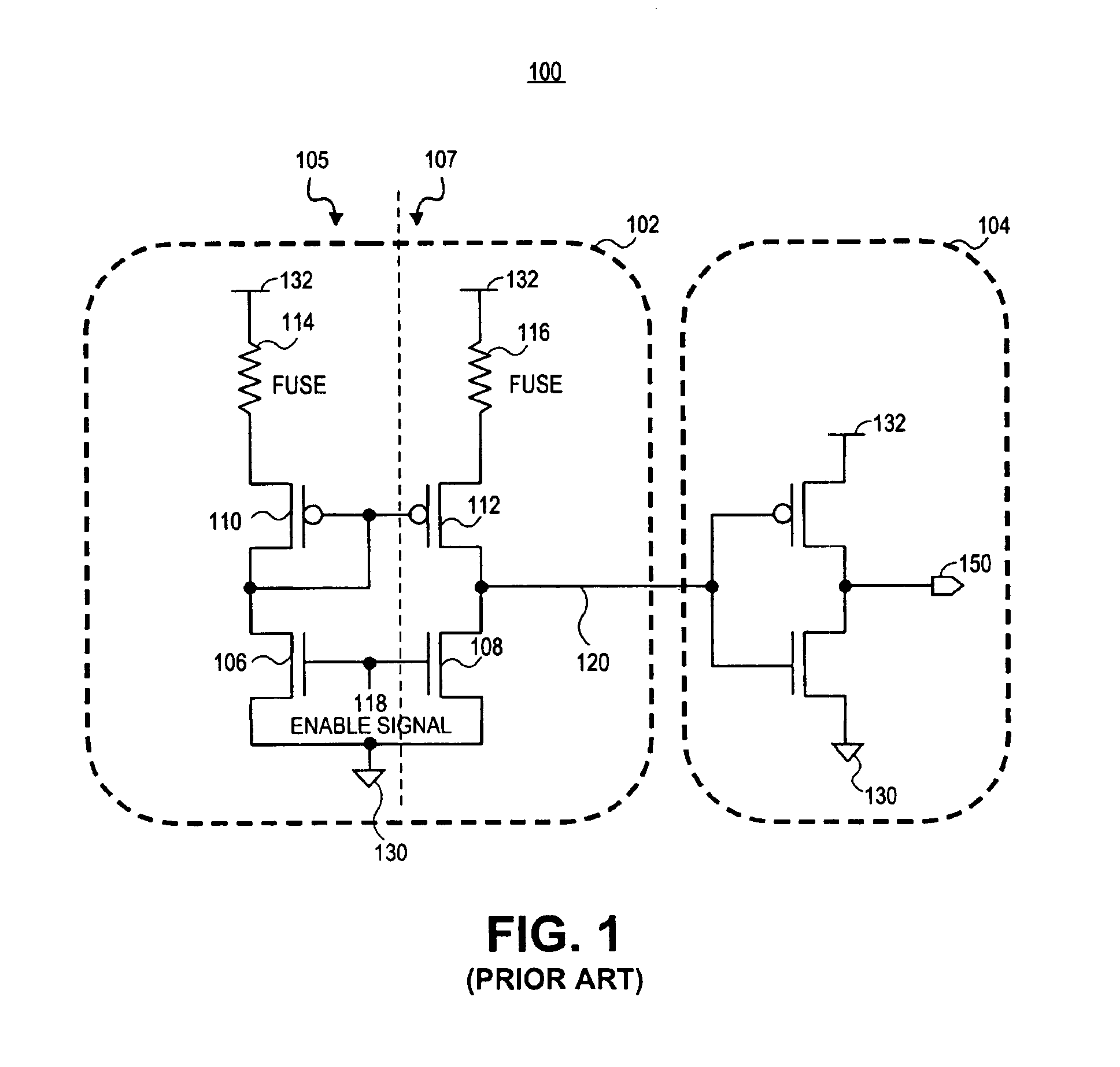
Sometimes the difference in resistance between a programmed fuse and an unprogrammed fuse is so small that the resistance difference is difficult to detect.
This is especially true for fuses with smaller geometries (e.g., line widths and device sizes), whose resistances can be harder to control in the manufacturing process.
Merely increasing the current in a fuse sensing circuit to increase sensitivity is not a viable approach.
If the current through an unprogrammed fuse is not low enough during sensing, the unprogrammed fuse may be erroneously programmed.
Additionally, reduced supply voltages in newer technologies results in smaller signals.
As a result, fuse sense circuits operating at the lower supply voltages may not have sufficient gain to ensure accurate sensing.
Integrated circuits also have natural mismatches among components.

Method used


Image

  • Fuse sense circuit
  • Fuse sense circuit
  • Fuse sense circuit

Examples


Embodiment Construction

[0015]A fuse sense circuit is described in detail herein. In the following description, numerous specific details are provided, such as particular currents, voltages, types of fuses, transistor types, and numbers of fuses to provide a thorough understanding of embodiments of the invention. One skilled in the relevant art will recognize, however, that the invention can be practiced without one or more of the specific details, or with other methods, components, etc. In other instances, well-known structures or operations are not shown or described in detail to avoid obscuring aspects of various embodiments of the invention.

[0016]Reference throughout this specification to “one embodiment” or “an embodiment” means that a particular feature, structure, or characteristic described in connection with the embodiment is included in at least one embodiment of the invention. Thus, the appearances of the phrases “in one embodiment” or “in an embodiment” in various places throughout this specifi...


PUM


Abstract

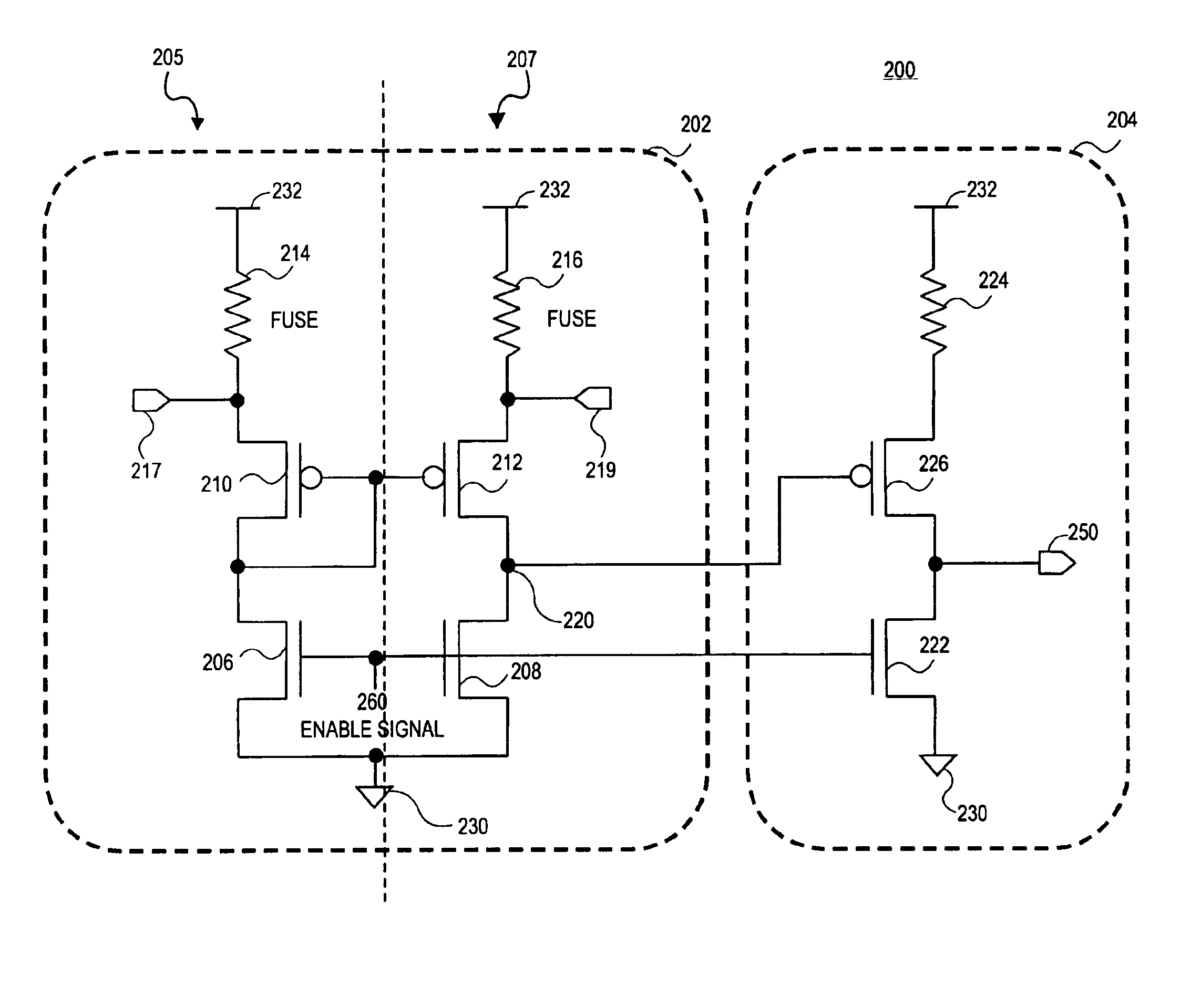
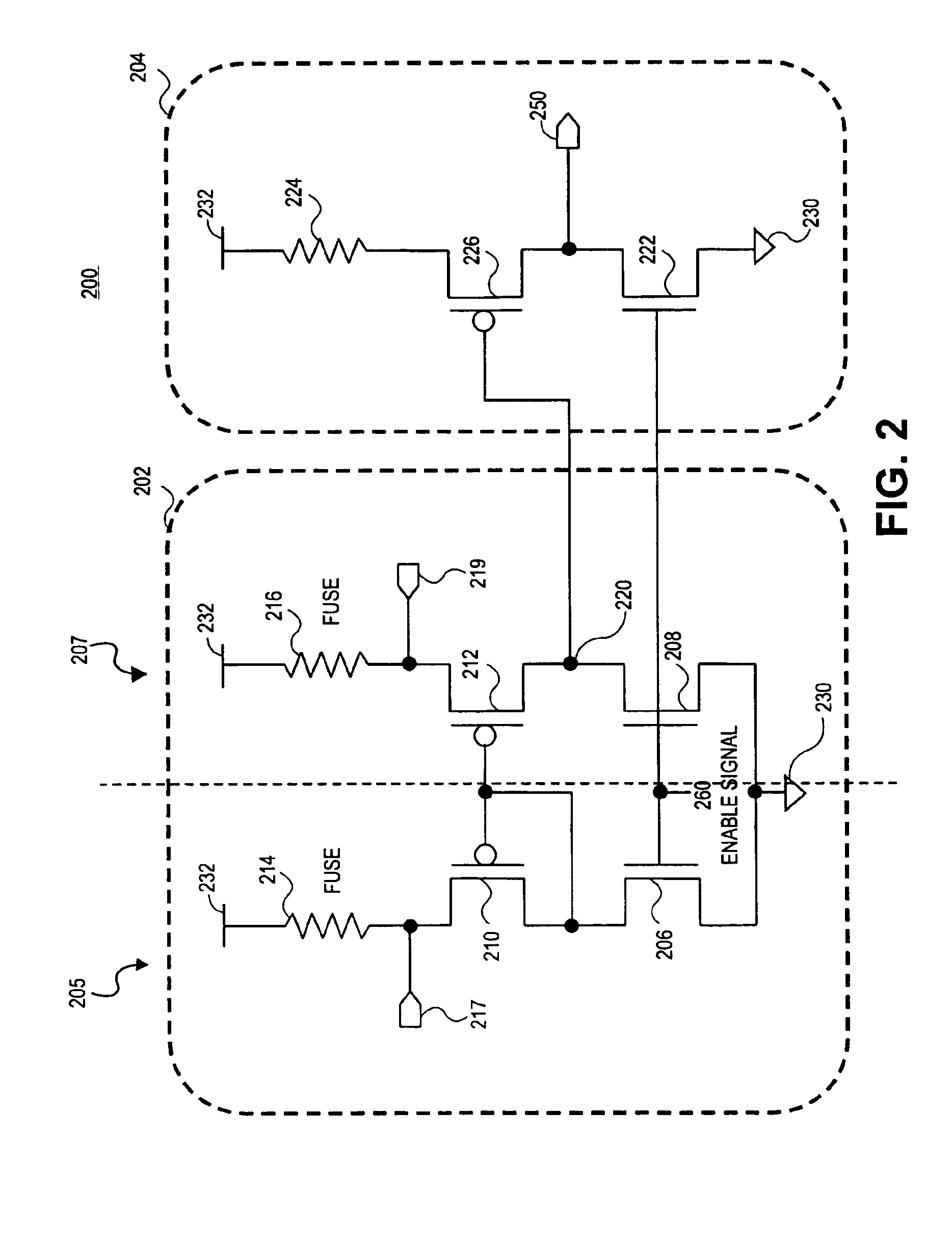
A fuse sense circuit has a sense amplifier and a post amplifier (gain stage). The sense amplifier has a reference branch and one or more sense (or fuse) branches. The fuse sense circuit determines the state of the fuses using safe currents and provides much higher gain than prior art. The post amplifier is a scaled replica of the reference branch or one of the sense branches in that the devices in the post amplifier maintain the same ratio as similar devices in the reference branch, and components in the post amplifier each matches components in the reference branch. The sense amplifier output is interpreted by the post amplifier's matched gain stage and has a trip point that sufficiently tracks the reference voltage. The result is reduced process and voltage sensitivity, which allows lower differential fuse resistance to be accurately detected with a non-ideal sense amplifier. Multiple gain stages may be added to multiple sense branches for redundancy and single-ended sensing.

Description

BACKGROUND OF THE INVENTION[0001]1. Field of the Invention[0002]The invention relates to the field of integrated circuit devices. More particularly, the invention relates to circuits for sensing the state of a fuse device.[0003]2. Background Information[0004]In many integrated circuits, fuses are used to store information, form connections, program elements for redundancy, store identification or other information, or trim analog circuits by adjusting the resistance of a current path. These functions are typically referred to as “programming” a fuse.[0005]To determine whether a fuse has been programmed, circuits that sense the state of fuses ususally distinguish between programmed and unprogrammed fuses by detecting a change in the resistance of the fuse device from a low to a high value. Sometimes the difference in resistance between a programmed fuse and an unprogrammed fuse is so small that the resistance difference is difficult to detect. This is especially true for fuses with s...

Claims


Application Information

Patent Timeline
IPC IPC(8): G01R19/00H03F3/45G11C17/18
CPCG11C17/18
Inventor PARKER, RACHAEL JADEDENHAM, MARTIN S.
Owner INTEL CORP
Learn More