
Technique for printing a color image

a color image and color technology, applied in the field of color image printing, can solve the problems of cumbersome and time-consuming requirement to change the color of the donor dye with a single head machine, and achieve the effect of enhancing the color uniformity of the image and enhancing the printed color imag

Inactive Publication Date: 2005-06-14
INTELLECTUAL VENTURES I LLC
View PDF13 Cites 22 Cited by
  • Summary
  • Abstract
  • Description
  • Claims
  • Application Information

AI Technical Summary

Benefits of technology

[0015]Embodiments of the present invention relate to a system, apparatus, computer program product and / or method, for enhancing a printed color image as perceived by a human viewer. The image is composed of a plurality of superimposed regular dot-patterns upon a planar surface. The surface moves in a first direction parallel to the surface. Each dot pattern has a fixed spatial frequency in the first direction (dots are substantially equidistant from each other in the first direction) and another fixed spatial frequency in a second direction (dots are substantially equidistant from each other in the second direction) perpendicular to the first direction. These two spatial frequencies for a particular dot pattern need not be equal and are not equal to spatial frequencies of the other pattern. Each one of the patterns is monochromatic and different in color from that of each of the other patterns. One of the regular dot patterns is intentionally misregistered with respect to another of the patterns in directions only parallel to and perpendicular to the first direction by virtue of its having different spatial frequencies from that of the other pattern in both the first direction and second direction, thereby obtaining a pattern misregistration. The pattern misregistration is controlled to obtain a particular misregistration having the property of enhancing the color image while the particular misregistration remains imperceptible to the viewer. The misregistration is designed to subdue color variations within an image, and from image to image, while producing no image artifacts visible to the viewer. Enhancing the color image includes enhancing the color uniformity of the image.
[0018]In a further feature, an improved color image on a movable planar surface using multiple arrays of dots is created. The surface moves in a first direction parallel to the surface. The image has at least enhanced color uniformity as perceived by a human viewer of the image. A first one of the arrays is created in a first color as a first colored array on the surface; the dots forming the first colored array are spaced at first predetermined distances from each other. A second one of the arrays is created in a second color as a second colored array generally superimposed on the first colored array; the dots forming the second colored array are spaced at second predetermined distances from each other. All of the first predetermined distances which are parallel to and perpendicular to the first direction and all of the second predetermined distances which are parallel to and perpendicular to the first direction are controlled to result in a particular intentional misregistration between the dots of the second colored array and the dots of the first colored array, the misregistration having the property of improving the color uniformity of the image for the viewer. A third one of the arrays is created in a third color as a third colored array, generally superimposed on the second colored array and said first colored array. The dots forming the third colored array are controlled to be spaced at third predetermined distances not aligned with the first or second array. When the colors printed are yellow, magenta and cyan, the predetermined distances chosen for printing yellow and cyan can be the same. (This is because the spectral overlap between yellow and cyan is typically insignificant. Magenta, the color obtained by absorbing green light, is the “middle” color in the spectrum and overlaps the others on both sides.)
[0021]In a particular embodiment, each element of the cyan-printing head and each element of the yellow-printing head deposit 400 dots per inch on the surface within the field of view of the image, with each respective one of the 400 dots per inch from the yellow-printing head intending to be deposited upon or directly upon its corresponding one of the 400 dots per inch from the first print head. Since there is minimal spectral overlap between these colors, although being subjected to a dot-on-dot procedure, precise registration of the yellow and cyan dots is unnecessary. Each element of the print head which prints magenta, is controlled to deposit 266 dots per inch on the surface throughout the field of view. In this embodiment, the first and third thermal print head's predetermined number of elements is 300 per inch each, and the second thermal print head's predetermined number of elements is 400 per inch. The intermingling of a column of 300 dots per inch by a row of 400 dots per inch pattern with a column of 400 dots per inch by a row of 266 dots per inch pattern over the field of view in this manner has the property of enhancing color uniformity of the image for the viewer, each one of the dots being individually indistinguishable to a naked eye of the viewer. Other colors and combinations of numbers of dots can be used.
[0022]It is therefore advantageous to use embodiments of the present invention in the production of images obtained through digital photography whereby a high rate of image production and enhanced image uniformity are achieved, while misalignment problems are minimized.
[0023]It is thus a general object of the present invention to provide an improved technique for printing images.
[0024]It is another general object of the present invention to provide an improved technique for creating color images produced through digital photography.

Problems solved by technology

As earlier discussed, the requirement to change donor dye color with a single head machine is very cumbersome and time consuming; this problem is avoided by use of a tandem head machine with a different color associated with each head, to be described next.

Method used


Image

  • Technique for printing a color image
  • Technique for printing a color image
  • Technique for printing a color image

Examples


Embodiment Construction

FIGS. 3&4—Three Head Machine and Timing

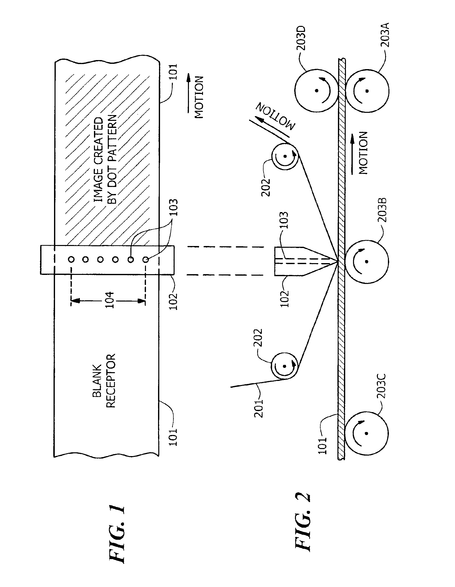
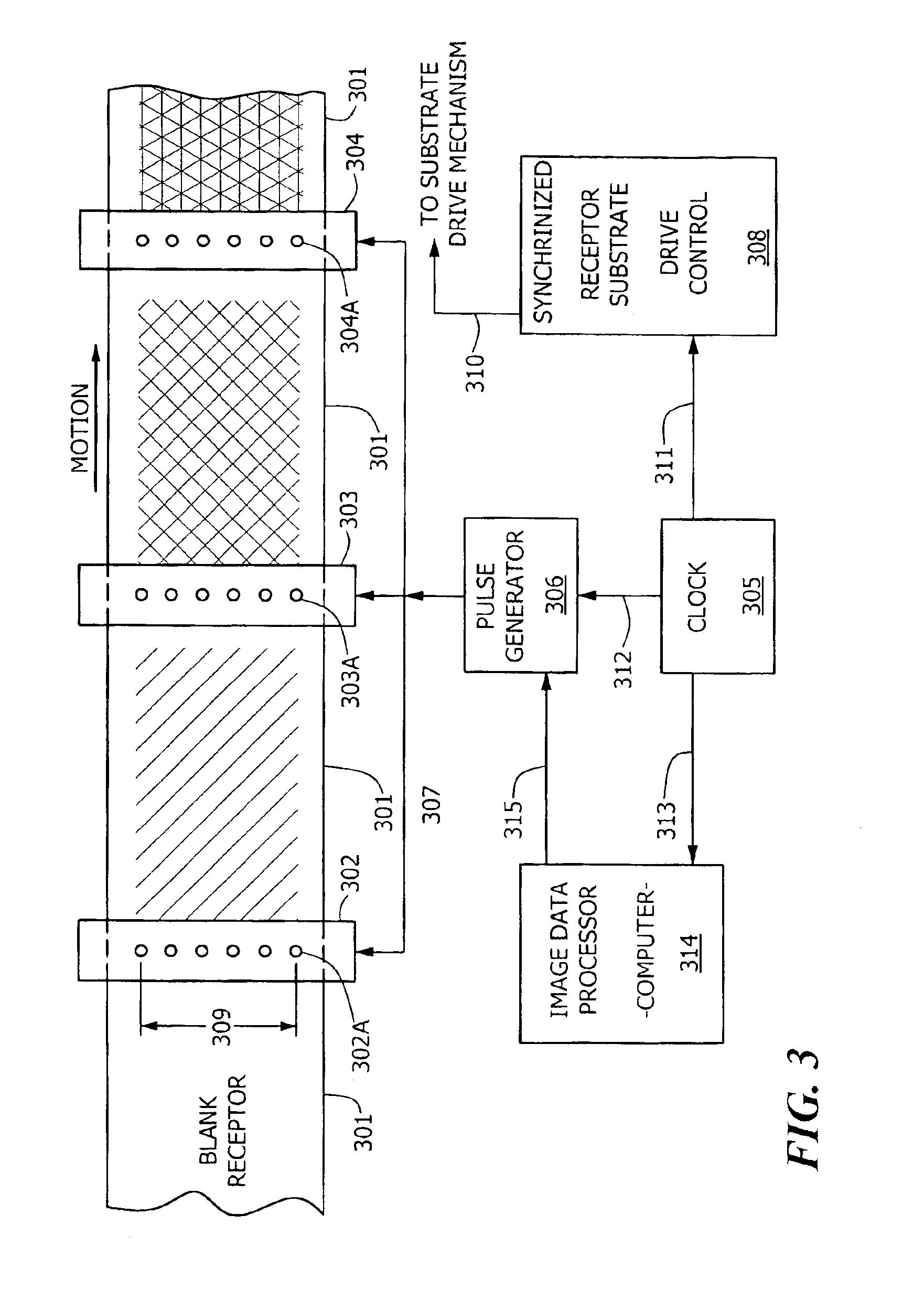
[0037]FIG. 3 is a plan view, schematic diagram of a three head thermal imaging machine of the type which can be employed in embodiments of the present invention. Receptor 301 moves from left to right in a first direction shown underneath three thermal print heads 302, 303, and 304. The portion of the receptor under the three heads can lie in a generally planar surface. Other receptor support configurations, such as those forming the receptor into a portion of a curved surface, such as a portion of a cylindricalsurface having circular cross section, or other curved surface having, for example an elliptical or arcuate cross section, etc. can be used without deviating from application of the principles of the present invention. Referring back to FIG. 2, it should be understood that receptor substrate 101 could have been arranged to slide or move over any curved surface with curvature in only one of two orthogonal spatial dimensions, such as cylind...


PUM


Abstract

A technique for optimizing or enhancing color images. Embodiments are disclosed for creating an enhanced color image, including the enhancement of perceived color uniformity. In a “dot-on-dot” registration scheme for producing color images, the dots need to be precisely superimposed on each other to provide optimum or enhanced images. The dot-on-dot registration produced by a single head thermal printer is generally acceptable, but a single head machine is very slow because multiple passes (reciprocation) are required to lay down multiple colors of dots. In a much faster multi-head or tandem thermal imaging system a serious problem of dot misalignment may cause moire patterns or other visual artifacts in the color images produced by dot patterns. A solution to this problem is disclosed herein which intentionally misregisters superimposed dots in a novel and particular manner to achieve image optimization. In a particular embodiment a first thermal print head has a first number of thermal elements energized at a first rate and a second thermal print head has a second number of thermal elements energized at a second rate. The numbers of thermal elements and rates of energization are selected to cause intentional misregistration at a high spatial frequency which is unnoticeable to the naked eye of a viewer of the image, thereby masking any unintentional mechanical misalignment of the print heads while maintaining imperceptible the intentional misregistration of the solution to the problem.

Description

BACKGROUND OF THE INVENTION[0001]1. Field of the Invention[0002]The present invention relates to creating images by techniques including a thermal imaging technique, and, more particularly, relates to a system, apparatus, computer program product and / or method for enhancing color uniformity of images produced by way of a printer having multiple thermal print heads.[0003]2. Description of Prior Art[0004]Many people enjoy reading the “Parade” section of their local Sunday newspaper and are usually enticed by the multicolored pictures on its first cover page. If one were to apply a magnifying glass to those pictures, the underlying dot patterns from which those pictures are composed would be readily discernable. This process of composing pictures by dot patterns is well established. Such patterns can be rendered by various methods including traditional offset printing, and digital imaging techniques such as electrophotographic, ink-jet and thermal imaging processes. In digital photogra...

Claims


Application Information

Patent Timeline
Patent Type & Authority Patents(United States)
IPC IPC(8): B41J2/21H04N1/50B41J2/525B41J2/355
CPCH04N1/506B41J2/2132
Inventor BOUCHARD, ALAINDEYOUNG, ANEMARIETELFER, STEPHEN J.VETTERLING, WILLIAM T.
Owner INTELLECTUAL VENTURES I LLC
Learn More