
Multi-domain liquid crystal display device with particular dielectric structures

a liquid crystal display and dielectric structure technology, applied in non-linear optics, instruments, optics, etc., can solve the problems of weak distortion of electric field needed to divide the pixel region, deterioration of display quality, etc., to achieve multi-domain effect, improve transmission, and stabilize texture in screen display

Inactive Publication Date: 2005-06-14
LG DISPLAY CO LTD
View PDF28 Cites 16 Cited by
  • Summary
  • Abstract
  • Description
  • Claims
  • Application Information

AI Technical Summary

Benefits of technology

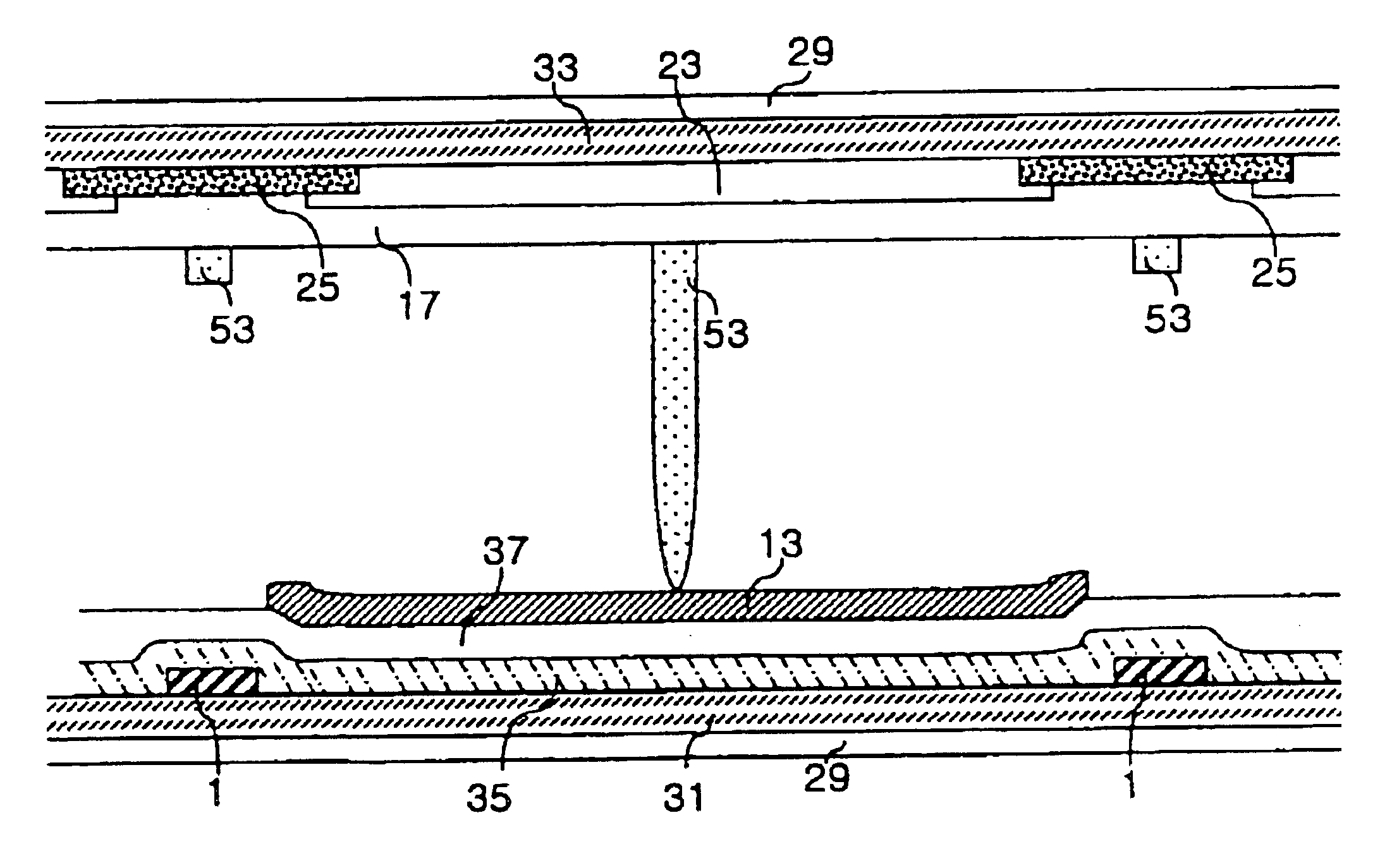
[0015]An object of the present invention is to provide a multi-domain LCD that has a dielectric frame in or around a divided pixel region, and has a special dielectric frame formed for maintaining an island-shape or a cell gap on the center of the divided pixel region. As a result, the stability of the texture in a screen display, the improvement of transmission and the multi-domain effect can be realized.

Problems solved by technology

Moreover, if the electrodes do not have an open area or the open area is narrow, the distortion of electric field needed to divide the pixel region becomes weak.
As a result, the quality of display is deteriorated.

Method used


Image

  • Multi-domain liquid crystal display device with particular dielectric structures
  • Multi-domain liquid crystal display device with particular dielectric structures
  • Multi-domain liquid crystal display device with particular dielectric structures

Examples


Embodiment Construction

[0029]Hereinafter, the multi-domain liquid crystal display device of the present invention is explained in detail by accompanying the drawings.

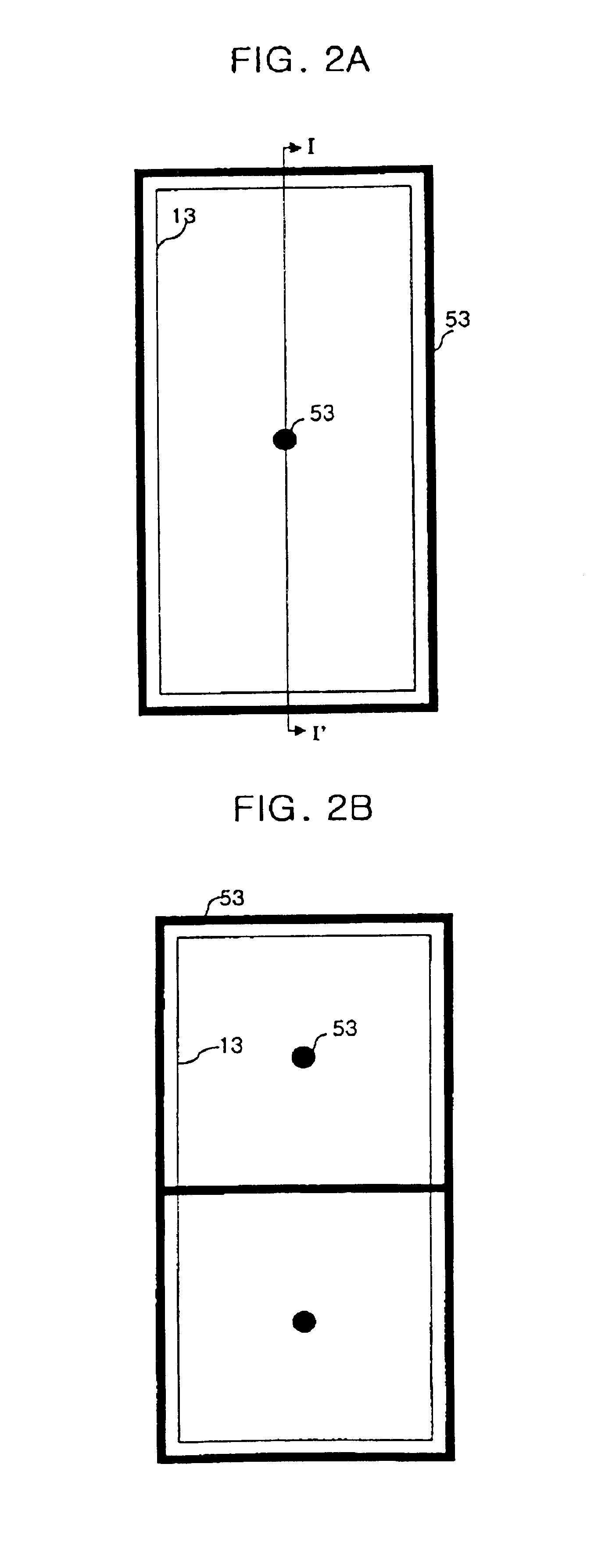
[0030]FIGS. 2A to 2D are plane views of the multi-domain liquid crystal display devices according to the first embodiment of the present invention, FIGS. 3A to 3D are plane views of the multi-domain liquid crystal display devices according to the second embodiment of the present invention, and FIGS. 4A, 4B, 4C, 5A, 5B and 5C are sectional views of the multi-domain liquid crystal display devices according to line I-I′ of FIG. 2A in the present invention.

[0031]As shown in the above figures, the multi-domain liquid crystal display device according to the present invention comprises first and second substrates 31, 33, a plurality of gate and data bus lines 1, arranged in the perpendicular and horizontal directions on the first substrate to divide the first substrate into a plurality of pixel regions.

[0032]The TFT is formed on each pixel region on...


PUM

PropertyMeasurementUnit
dielectric constantaaaaaaaaaa
electric fieldaaaaaaaaaa

Abstract

The present multi-domain liquid crystal display device includes first and second substrates facing each other; a liquid crystal layer between the first and second substrates; a first dielectric frame on one side of the pixel region; a second dielectric frame on another side of the pixel region; and a third dielectric frame between the first dielectric frame and the second dielectric frame.

Description

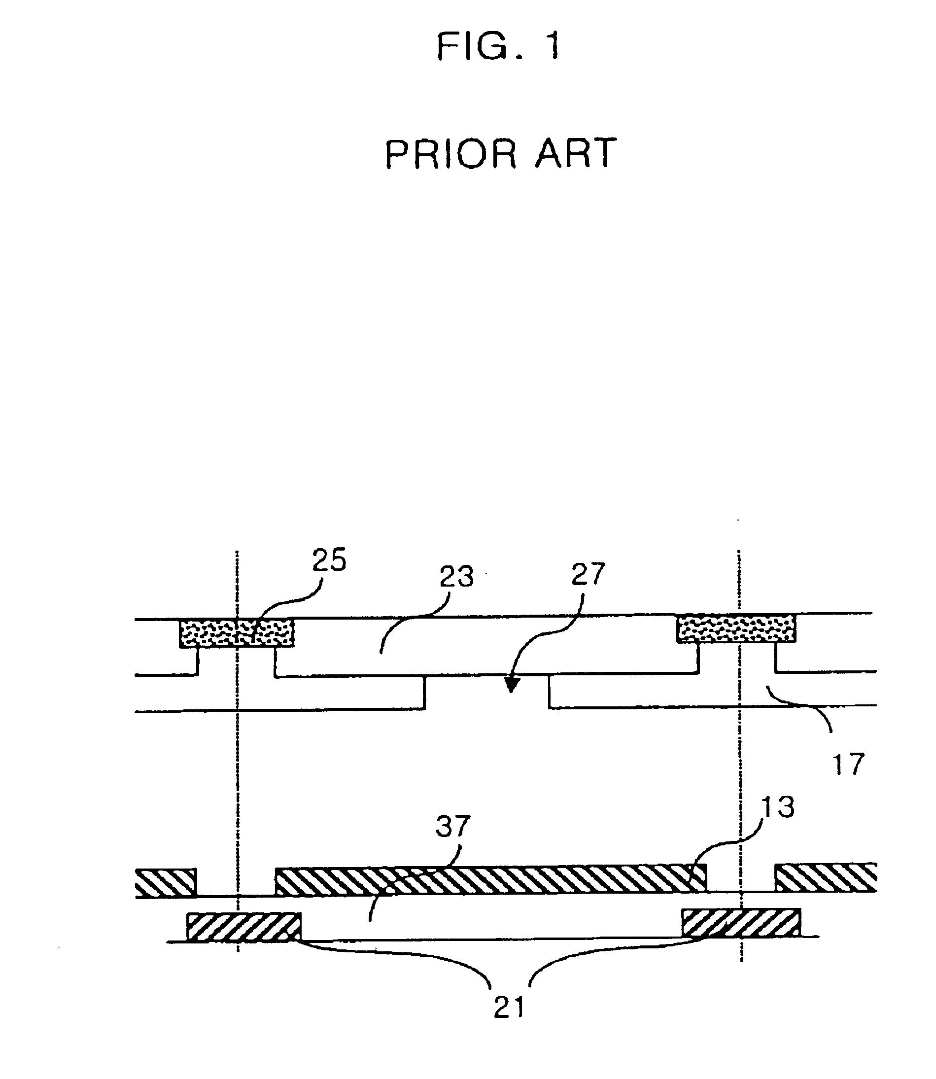
CROSS REFERENCE TO RELATED APPLICATIONS[0001]The application is a Continuation-in-Part of U.S. patent application Ser. No. 09 / 448,276 filed on Nov. 24, 1999 and this application also claims the benefit of Korean Patent Application No. 2000-1793, filed on Jan. 14, 2000, which are hereby incorporated by reference for all purposes as if fully set forth herein.BACKGROUND OF THE INVENTION[0002]1. Field of the Invention[0003]The present invention relates to a liquid crystal display device (LCD), and more particularly, to a multi-domain liquid crystal display device having a dielectric frame in or around divided pixel region, and having a special dielectric frame on the center of the divided pixel region.[0004]2. Description of the Related Art[0005]Recently, a LCD has been proposed where the liquid crystal is not aligned, and the liquid crystal is driven by side electrodes insulated from pixel electrodes. FIG. 1 is a sectional view of pixel unit of the conventional LCDs.[0006]Regarding con...

Claims


Application Information

Patent Timeline
Patent Type & Authority Patents(United States)
IPC IPC(8): G02F1/13G02F1/1333G02F1/1337
CPCG02F1/133707G02F1/133753
Inventor KIM, KYEONG JINLEE, YUN BOK
Owner LG DISPLAY CO LTD
Learn More