Power supply apparatus and methods with power-factor correcting bypass mode

Inactive Publication Date: 2005-06-14
EATON INTELLIGENT POWER LIMITED
View PDF21 Cites 107 Cited by
  • Summary
  • Abstract
  • Description
  • Claims
  • Application Information

AI Technical Summary

Benefits of technology

[0006]According to some embodiments of the invention, a power supply apparatus, such as an uninterruptible power supply, includes an AC input configured to be connected to an AC power source and an AC output. The apparatus also includes an AC/DC converter circuit, e.g., a boost rectifier circuit, with an input coupled to the AC input. The apparatus further includes a DC/AC converter circuit, e.g., an inverter circuit, configured to be coupled between an output of the AC/DC converter circuit and the AC output. A bypass circuit is operative to establish a coupling between the AC input and the AC output in a first (e.g., bypassed) state and to interrupt the coupling in a second (e.g., “on line”) state. The AC/DC converter circuit is operative to control current at the AC input when the bypass circuit is in the first state, such that, for example, a power factor at the AC input port may be corrected. In this manner, the AC/DC converter circuit may act as a line conditioner in the bypassed state.
[0007]In further embodiments of the invention, the AC/DC converter circuit comprises a current reference signal generating circuit operative

Problems solved by technology

However, such an approach may be compromised if the AC power source is subject to small but frequent excursions outside of the power quality criteria, as may be the case, for example, in systems powered by an unsteady AC power source, such as

Method used


Image

  • Power supply apparatus and methods with power-factor correcting bypass mode
  • Power supply apparatus and methods with power-factor correcting bypass mode
  • Power supply apparatus and methods with power-factor correcting bypass mode

Examples


Embodiment Construction

[0013]Specific exemplary embodiments of the invention now will be described with reference to the accompanying drawings. This invention may, however, be embodied in many different forms and should not be construed as limited to the embodiments set forth herein; rather, these embodiments are provided so that this disclosure will be thorough and complete, and will fully convey the scope of the invention to those skilled in the art. In the drawings, like numbers refer to like elements. It will be understood that when an element is referred to as being “connected” or “coupled” to another element, it can be directly connected or coupled to the other element or intervening elements may be present.

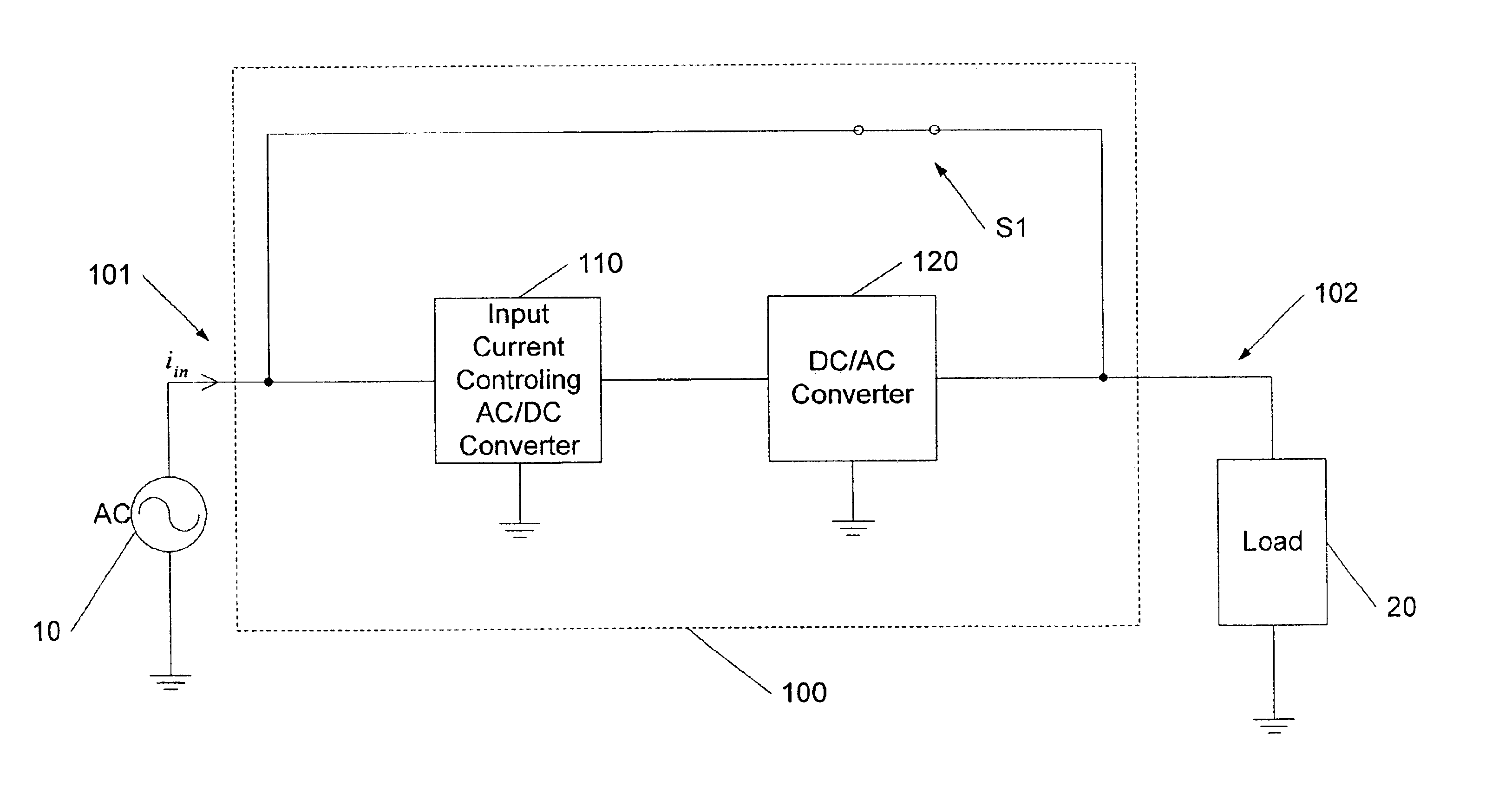
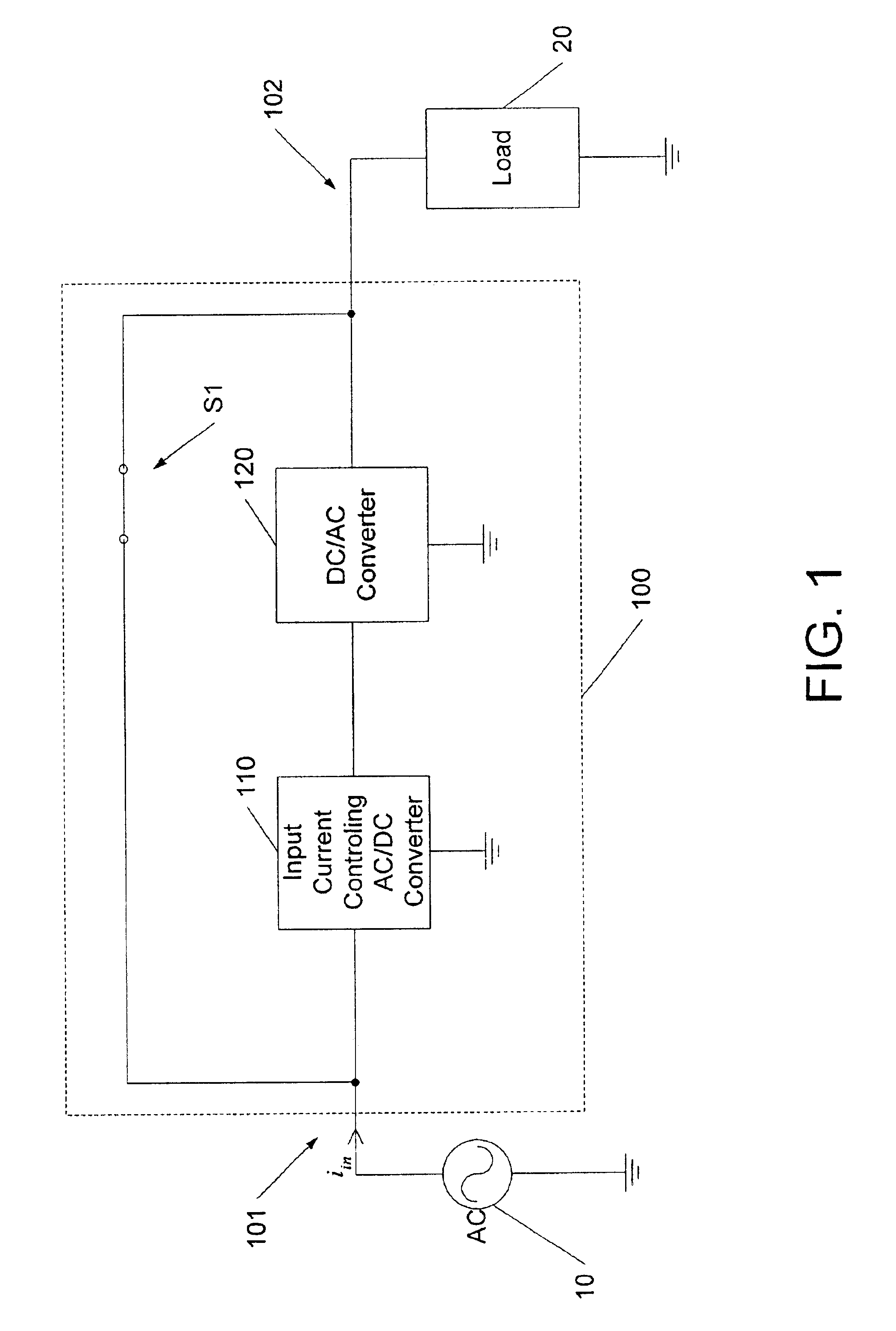
[0014]FIG. 1 illustrates a power supply apparatus 100 according to some embodiments of the invention The power supply apparatus 100 includes an input 101 configured to be coupled to an AC power source 10, and an output 102 configured to be coupled to a load 20. In a first mode of operation of the...


PUM


Abstract

A power supply apparatus, such as an uninterruptible power supply, includes an AC input configured to be coupled to an AC power source and an AC output. The apparatus also includes an AC/DC converter circuit, e.g., a boost rectifier circuit, with an input coupled to the AC input. The apparatus further includes a DC/AC converter circuit, e.g., an inverter circuit, configured to be coupled between an output of the AC/DC converter circuit and the AC output. A bypass circuit is operative to establish a coupling between the AC input to the AC output in a first (e.g., bypassed) state and to interrupt the coupling in a second (e.g., “on line”) state. The AC/DC converter circuit is operative to control current at the AC input when the bypass circuit is in the first state. For example, the AC/DC converter circuit may be operative to control current at the AC input to correct a power factor at the AC input port when bypassed, such that the AC/DC converter circuit may act as a line conditioner in the bypassed state.

Description

BACKGROUND OF THE INVENTION[0001]The invention relates to power conversion apparatus and methods, and more particularly, to power conversion apparatus and methods for use, for example, in redundant power supply systems such as uninterrupted or uninterruptible power supplies (UPSs).[0002]Power supply circuits are commonly used in equipment such as UPSs, motor drives, and other applications. Conventional UPSs use a variety of different circuit topologies, including standby, line-interactive and on-line topologies. Generally, each of these topologies has advantages and disadvantages and, accordingly, selection of a particular topology is typically governed by the needs of the application.[0003]Many UPSs use an online topology. For example, a typical online UPS includes an AC / AC converter that produces an AC output voltage at a load from an AC input voltage provided by an AC power source such as a utility, using a DC link that can isolate the load from disturbance and other degradation ...

Claims


Application Information

Patent Timeline
IPC IPC(8): H02J9/06H02J3/32H02J3/28H02M1/00H02M1/42
CPCH02J3/32H02J9/062H02M1/4258Y02B70/126H03F2200/351Y02B70/10
Inventor TAIMELA, PASI S.
Owner EATON INTELLIGENT POWER LIMITED
Why Eureka
Try Eureka