
Method for a network device inserted between point to point connected stations to automatically negotiate communication parameters between the stations

a network device and communication parameter technology, applied in the field of data networking, can solve the problems of impracticality of attaching a repeater between every server and switch port to promiscuously monitor data traffic, impossible to attach a probe to that segment to promiscuously monitor network,

Inactive Publication Date: 2005-06-14
RPX CLEARINGHOUSE
View PDF10 Cites 18 Cited by
  • Summary
  • Abstract
  • Description
  • Claims
  • Application Information

AI Technical Summary

Problems solved by technology

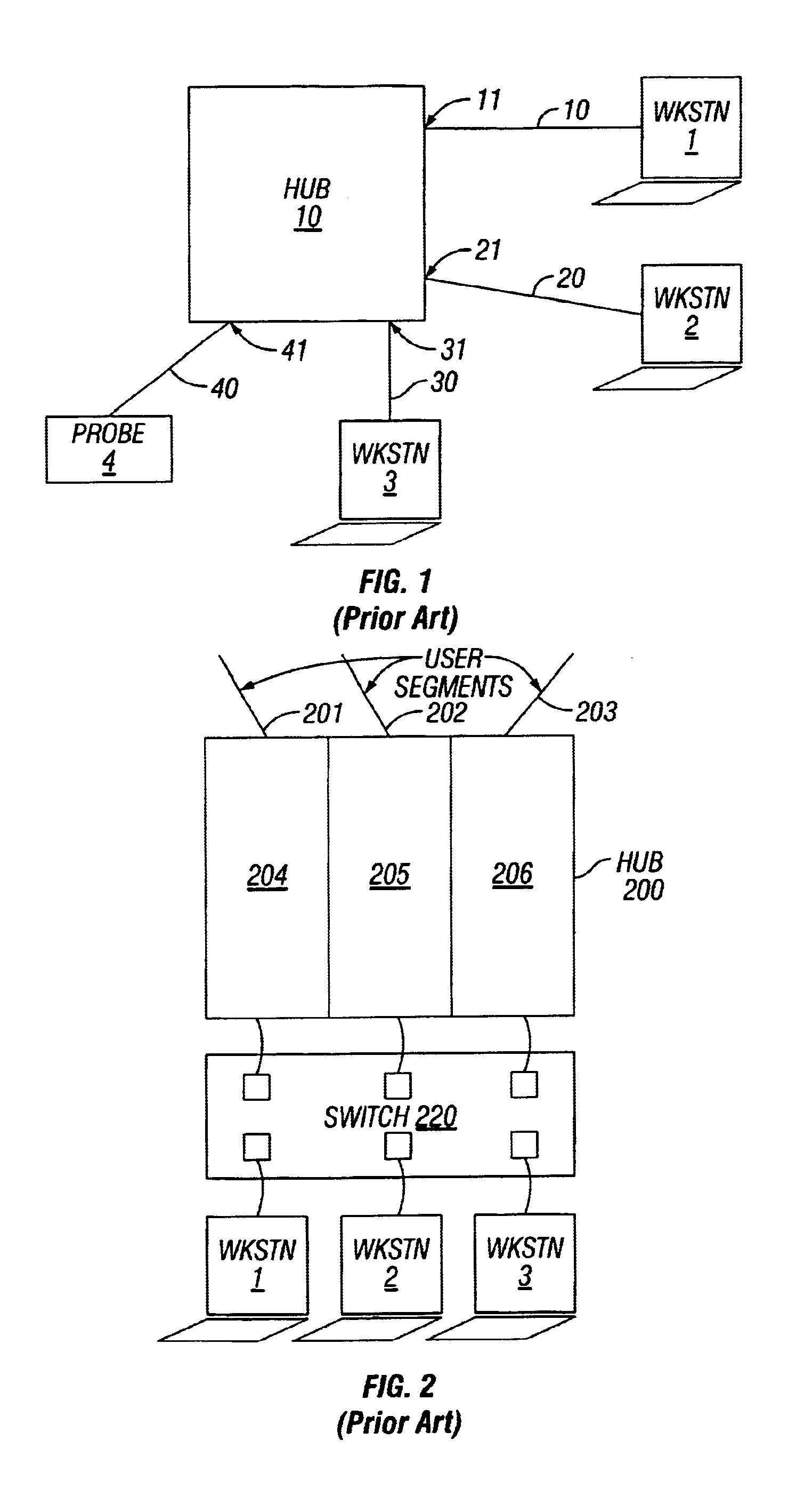
The problem, however, in monitoring network performance in such an environment utilizing probes was that a single probe was required for each segment in order to promiscuously monitor the data traffic on that segment.
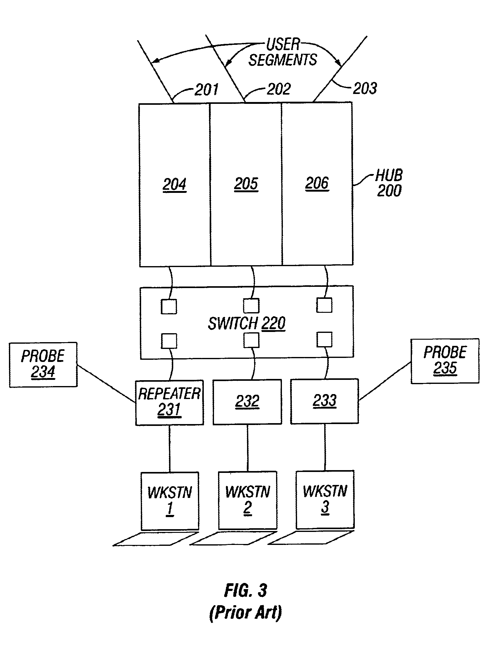
With reference to FIG. 3, as the data networks became highly segmented, it became evident that it was impractical to attach a probe to each segment in the network to promiscuously monitor all traffic.
In a single station network segment, it was impossible to attach a probe to that segment to promiscuously monitor network traffic because only a single port was necessarily available for coupling the segment to the switch.
In such a situation, it becomes impractical to attach a repeater between every server and switch port to promiscuously monitor data traffic, due to the increased cost, space, and asset management responsibilities encountered as a result of the additional equipment.
This process would be highly disrupting to data communications in the network.
By the time the probe was operable, the performance problem may well have disappeared.
However, when a prior art probe is inserted between such nodes in a point to point link, the nodes are no longer able to directly negotiate the highest common mode of operation between them by means of the Auto-Negotiation function.

Method used


Image

  • Method for a network device inserted between point to point connected stations to automatically negotiate communication parameters between the stations
  • Method for a network device inserted between point to point connected stations to automatically negotiate communication parameters between the stations
  • Method for a network device inserted between point to point connected stations to automatically negotiate communication parameters between the stations

Examples


Embodiment Construction

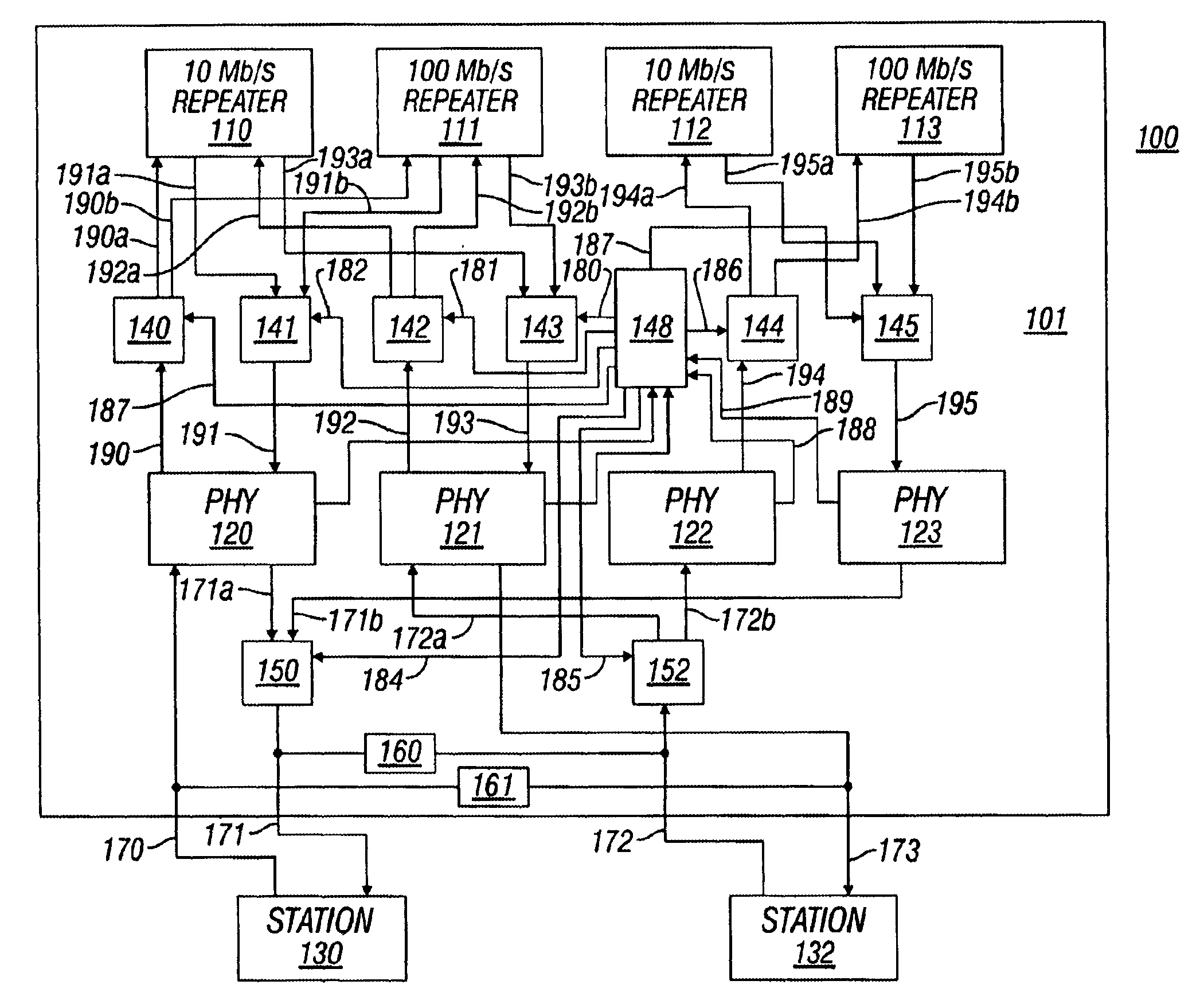
[0026]The present invention provides a method and apparatus embodied in a network probe inserted between two nodes connected via a point-to-point link for negotiating and synchronizing enhanced modes of operation between the two nodes. In the following description, numerous specific details are set forth in order to provide a thorough understanding of the present invention. It will be apparent, however, to one of ordinary skill in the art that the present invention may be practiced without these specific details. In other instances, well-known architectures, circuits, and techniques have not been shown to avoid unnecessarily obscuring the present invention.

[0027]In alternative embodiments, the present invention may be applicable to implementations of the invention in integrated circuits or chip sets, wireless implementations, switching systems products and transmission systems products. For purposes of this application, the terms switching systems products shall be taken to mean pri...


PUM


Abstract

A network probe inserted between two nodes in point-to-point link synchronizes modes of operation between the two nodes. The probe utilizes IEEE 802.3u Clause 28 Auto-Negotiation to detect and advertise corresponding information regarding modes of operation for the nodes between which it is inserted in the point-to-point link, to achieve a highest priority common mode of operation between the nodes.

Description

COPYRIGHT NOTICE[0001]Contained herein is material that is subject to copyright protection. The copyright owner has no objection to the facsimile reproduction of the patent disclosure by any person as it appears in the Patent and Trademark Office patent files or records, but otherwise reserves all rights to the copyright whatsoever.BACKGROUND OF THE INVENTION[0002]1. Field of the Invention[0003]The present invention relates to data networking. In particular, the present invention relates to a method and apparatus for a network probe to synchronize enhanced modes of operation between two nodes connected via a point-to-point link, into which link the network probe is inserted.[0004]2. Description of the Related Art[0005]With reference to FIG. 1, prior art data networks generally utilized one or more shared media hubs, e.g., hub 10. Multiple nodes, or end user workstations, e.g., workstations 1, 2 and 3, were coupled to a shared communications that was, in turn, coupled to a port on th...

Claims


Application Information

Patent Timeline
Patent Type & Authority Patents(United States)
IPC IPC(8): H04L12/26H04L29/06
CPCH04L29/06H04L43/12H04L69/24H04L9/40
Inventor MOSKOVICH, REUVENSHVIRSKY, YUVALTROST, ARIE
Owner RPX CLEARINGHOUSE
Learn More