
Method of multi selection coherent detection and device thereof

Inactive Publication Date: 2005-06-14
HUAWEI TECH CO LTD
View PDF9 Cites 2 Cited by
  • Summary
  • Abstract
  • Description
  • Claims
  • Application Information

AI Technical Summary

Benefits of technology

[0027]The object of the present invention addressed the problems existing in several detection methods listed above, and provides a method and a device for multi-selection coherent detection, in order to reduce the influence of the phase rotation caused by the frequency shift, and to improve the signal detection probability.

Problems solved by technology

Otherwise, the performance of the signal detection will inevitably be affected.
A good detection result can only be obtained by using such detection method when the phase of the received signal varies not so significant within the length L. It is difficult to achieve a phase of the received signal that does not vary significantly within the length L, under certain communication environments.
However, even when the phase of the received signal may be maintained constant within L (I>Snoncoh), then the detection performance loss of the non-coherent detection method will be smaller than the gain obtained from suppressing the phase rotation.
In general, it is worse than the coherent detection method of Method 1.
The detection performance loss of the differential detection method itself is also smaller than the gain obtained from suppressing the phase rotation.
In general, it is worse than the detection performance of the coherent detection method of Method 1.
The implementation of this method is rather difficult, and the optimum detection performance can not be obtained yet.
This may cause the coherent results to cancel each other out.
However, in the case of a low frequency shift, Method 1 also has the condition of maintaining the signal phase as a constant within the coherent length L. At this time, comparing the non-coherent of Method 2 with Method 1, a certain performance loss may exist.
However, in the case of low frequency shift, the performance loss will be larger than that of Method 1.
Although a better performance can be achieved by using Method 4 in the case of a variety of Doppler frequency shift, it is complicated by using the method of the protocol limitation.
By using the detection method, the Doppler frequency shift estimate module is required, so that, it is difficult to ensure accuracy.

Method used


Image

  • Method of multi selection coherent detection and device thereof
  • Method of multi selection coherent detection and device thereof
  • Method of multi selection coherent detection and device thereof

Examples


Embodiment Construction

[0039]The coherent detection method according to the present invention comprises following steps: the length L used for the signal detection is divided into Nmulticoh segments of multi coherent segments, the coherent accumulating will be performed within each segment, then total Nmulticoh coherent results can be obtained, they will be denoted as Xi (i=0 . . . Nnoncoh−1); assuming that the signal is divided into segments with equal spaces, then the length of each segment will be Smulticoh=L / Nmulticoh: Xm=∑k=0Smulticoh-1⁢(Y⁡(m*Smulticoh+k)*X*(m*Smulticoh+k)),⁢m=0⁢ ⁢…⁢ ⁢Nmulticoh-1(10)

[0040]And then, various possible phase adjustments may be performed on those Nmulticoh coherent results respectively. (The number of the possible phase adjustment will be denoted as P.) The adjustment results will be denoted as Yi,j (i=0 . . . Nmulticoh−1, j=0 . . . P−1). A value of the adjustment result will be selected from the adjustment results on which to perform various possible combinations. Then t...


PUM


Abstract

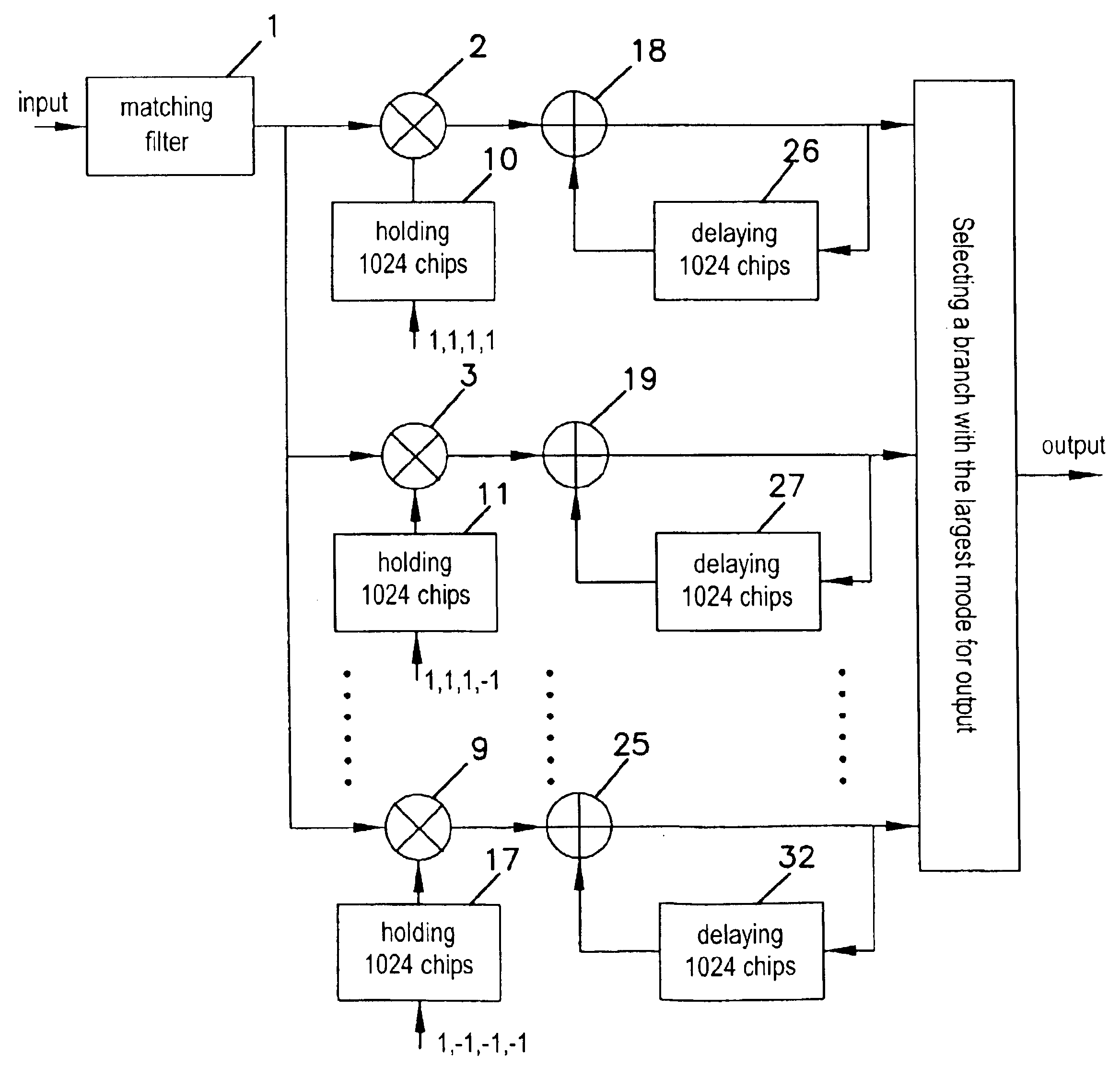
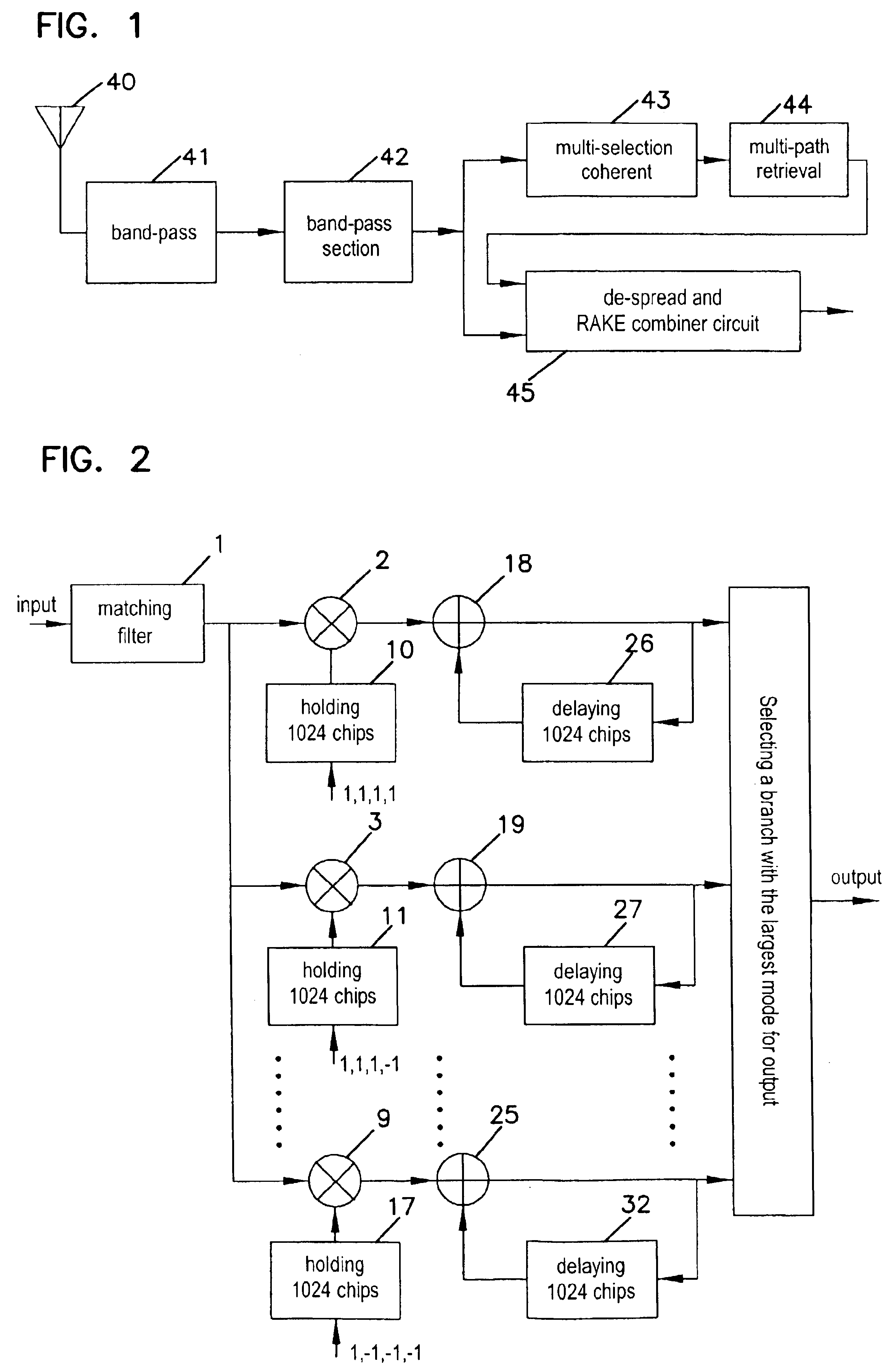
A method and device used in wireless mobile communication for multi-selection signal detection. In order to minimize the influence of frequency shift and phase rotation that reduces signal detection performance, the total number of samples used for the signal detection may be divided into an equal number of segments, on which the coherent accumulating sum is calculated. Various possible combinations will be made according to each coherent result. The combinations may then be coherent accumulated again. Finally, the optimum results may be selected as the detection results. To accomplish this result, the input signal is input to the matched filter unit, whose output will be sent to each branch unit. The phase adjustment and the coherent accumulation of the signal will be performed in each respective branch unit, and then sent to the branch selection unit where the branch output with the largest mode is selected as the output.

Description

CROSS REFERENCE TO RELATED APPLICATIONS[0001]This application is a 35 U.S.C. 371 of PCT application PCT / CN00 / 00151 filed Jun. 12, 2000, which claims priority on application 99124113.4 filed on Nov. 24, 1999 in China.FIELD OF THE INVENTION[0002]The present invention relates to a signal detection of the wireless mobile communication. More particularly, it relates to a method and its device for a multi-selection coherent detection.BACKGROUND OF THE INVENTION[0003]It is well known that the received signal may be affected by the so-called Doppler effect in the wireless mobile communication, and a Doppler frequency shift may be produced with respect to the transmittal signal. The size and the feature of the frequency shift may be determined by the relative motion between the transmitter and the receiver, and the environment of the signal transmission. However, phase rotation, even the phase reversion, may occur on the received wireless communication transmitting signal. Therefore, the inf...

Claims


Application Information

Patent Timeline
IPC IPC(8): H04B1/707H04J13/00H04B1/7115
CPCH04B1/7113H04B1/7093H04L27/227
Inventor LI, HUAJIA
Owner HUAWEI TECH CO LTD
Learn More