Terminals having sub-band substitute signal control in optical communication systems

a technology of optical communication system and sub-band substitute signal, applied in the field of optical communication, can solve the problems of increasing the cost of providing a substitute signal laser for each channel in tandem, and the use of a more delicate balance of substitute signals

Inactive Publication Date: 2005-06-14
OPTIC153 LLC
View PDF47 Cites 10 Cited by
  • Summary
  • Abstract
  • Description
  • Claims
  • Application Information

AI Technical Summary

Benefits of technology

[0007]In yet another aspect of the invention, a WDM optical network includes a control circuit, coupled to the monitoring circuit, which determines if a signal channel is unused or inoperable based on the detected wavelengths and power levels of the data signals detect...

Problems solved by technology

As a result, a more delicate balance of substitute signals is used to maintain the system performance of the Raman amplifier....

Method used


Image

  • Terminals having sub-band substitute signal control in optical communication systems
  • Terminals having sub-band substitute signal control in optical communication systems
  • Terminals having sub-band substitute signal control in optical communication systems

Examples


Embodiment Construction

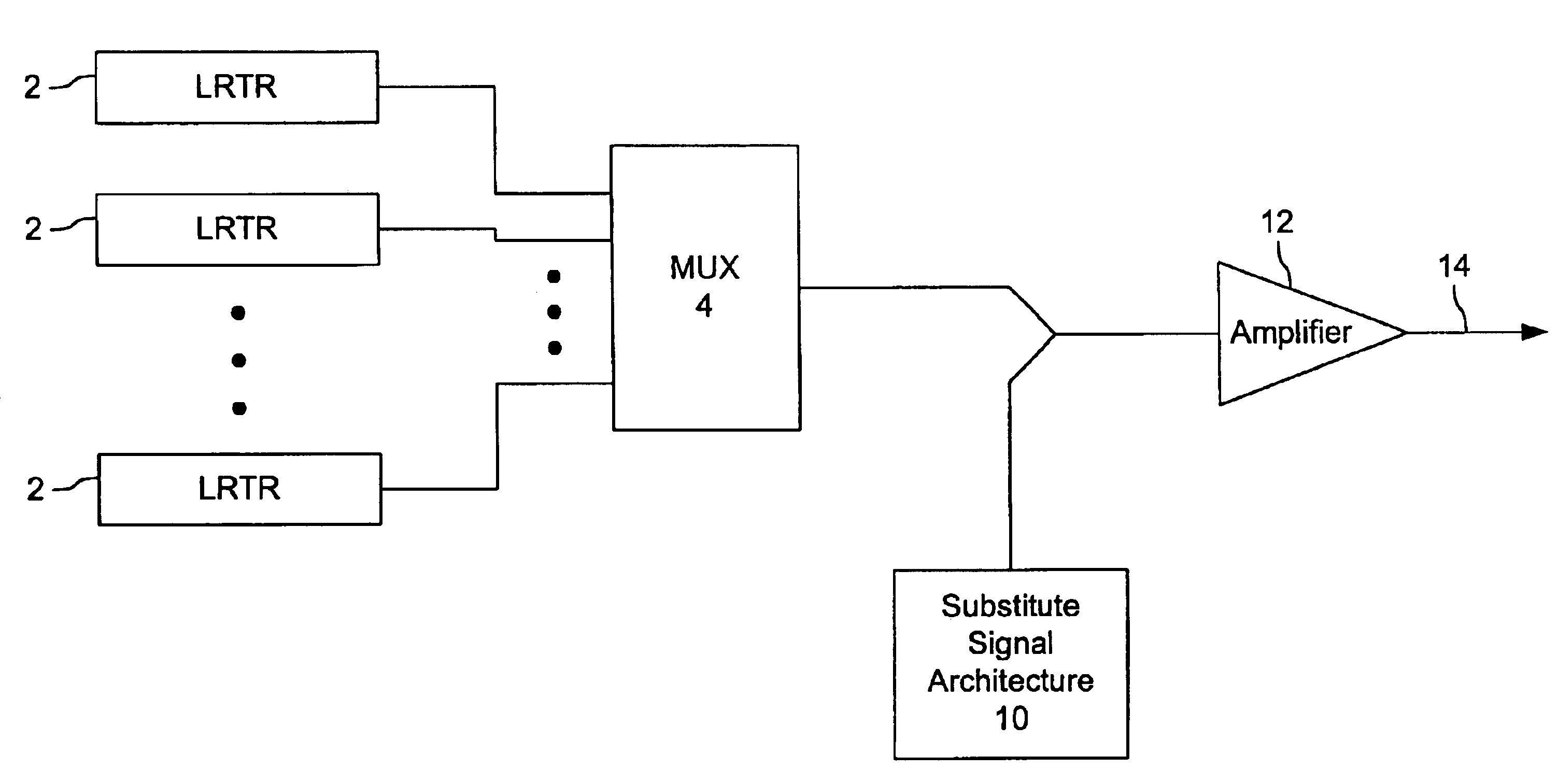
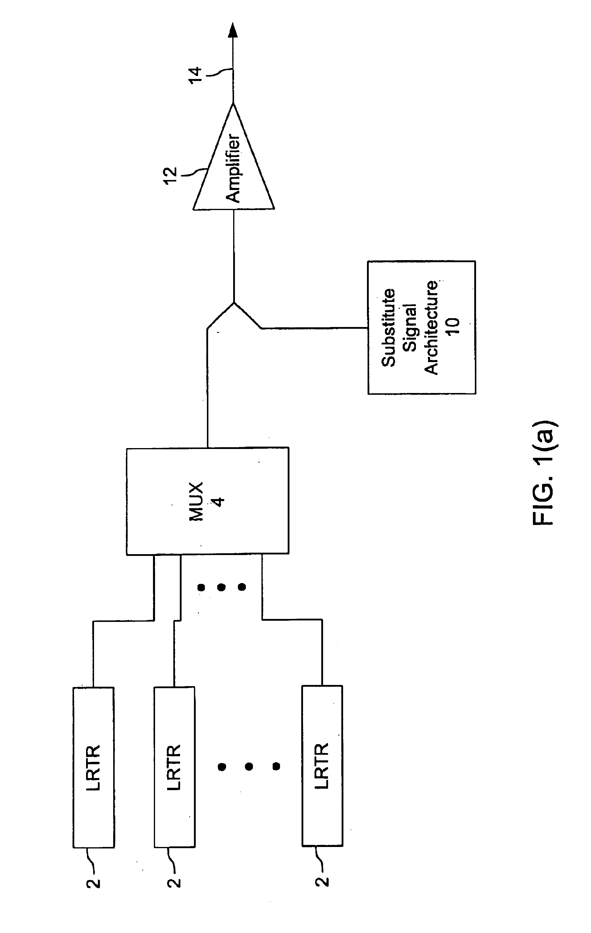
[0017]FIG. 1(a) is a block diagram of the transmit portion of a terminal unit including substitute signal architectures consistent with the present invention. Therein, a plurality of long reach transceivers (LRTRs) 2 each generate the optically modulated data signals to be transmitted by the terminal unit. These wavelength channels are wavelength division multiplexed by unit 4 to form a composite signal. Substitute signals are coupled to the multiplexed signal from substitute signal architecture 10, prior to being amplified for transmission by amplifier 12 and transmitted over, e.g., submarine or terrestrial cable 14. Those skilled in the art will appreciate that the multiplexing of data signals can be performed in stages if desired prior to adding the substitute signals.

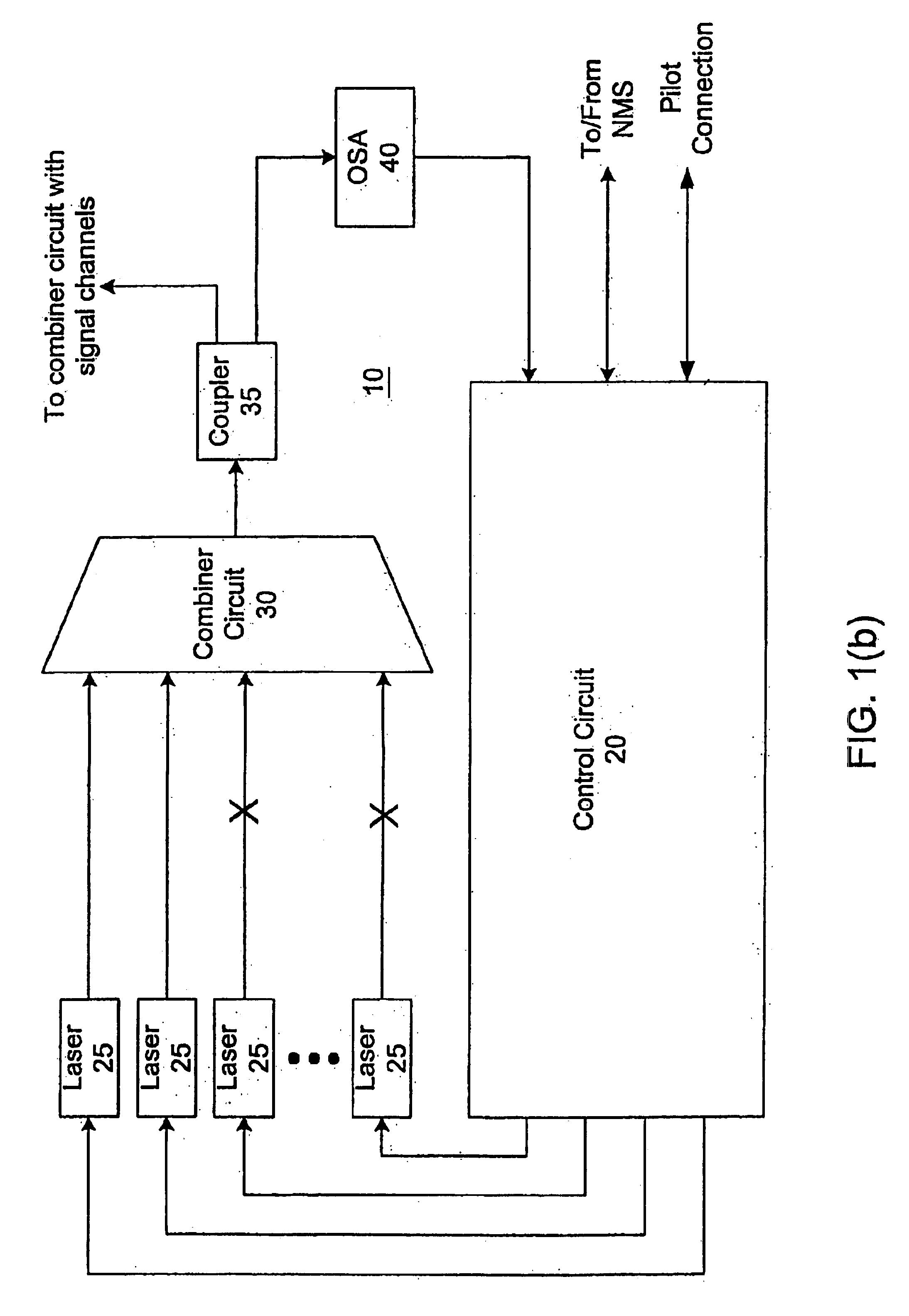
[0018]FIG. 1(b) is a block diagram of a substitute signal architecture 10 consistent with the present invention. The substitute signal architecture 10 is preferably implemented in a DWDM optical network. As shown in...


PUM


Abstract

A wavelength division multiplexed (WDM) optical network includes a plurality of optical transmitters, each optical transmitter generating a data signal sent over a respective one of a plurality of signal channels, the plurality of signal channels being divided into a number of sub-bands where each sub-band includes at least two signal channels, and a plurality of substitute signal transmitters, the number of substitute signal transmitters being equal to the number of sub-bands, each substitute signal transmitter generating a substitute signal which provides loading in a corresponding sub-band. The WDM optical network also includes a combining circuit which combines the data signals output from the plurality of optical transmitters and the substitute signals output from the plurality of substitute signal transmitters into a WDM signal, and an optical transmission fiber which receives the WDM signal from the combining circuit.

Description

FIELD OF THE INVENTION[0001]The present invention relates generally to optical communications, and more particularly to a system for maintaining amplifier saturation in a wavelength division multiplexed (WDM) optical communication system.BACKGROUND OF THE INVENTION[0002]In a dense wavelength division multiplexed (DWDM) system having a high number of signal channels, the initially deployed system typically does not have all of the signal channels fully populated. The number of signal channels that are populated depends upon several factors including the amount of capacity initially required in the DWDM system. To make the amplifiers in the system operational during the lifetime of the system, from initial deployment at less than capacity to full capacity after upgrades, a substitute signal may be used to fill one or more empty channels to maintain the saturation (and other) performance characteristics of the amplifier. In conventional narrowband Erbium doped fiber amplifier DWDM syst...

Claims


Application Information

Patent Timeline
IPC IPC(8): H04B10/155H04J14/02H04B10/152
CPCH04B10/506H04J14/02H04J14/0221H04J14/0246H04J14/0297H04J14/0279H04J14/0226
Inventor YU, ZHENGCHENSHIEH, WILLIAMCLARK, JR., THOMAS R.PETRICEVIC, VLADIMIR
Owner OPTIC153 LLC
Why Eureka
Try Eureka