Method and system for computer aided manufacturing

a computer and manufacturing technology, applied in the field of computer aided design and computer aided manufacturing, can solve the problems of not getting knowledge back to either the manufacturing engineer or the design engineer, affecting the overall machining process, so as to achieve the effect of improving programming and not so limited in the scope of invention

Inactive Publication Date: 2005-06-14
HEXAGON TECH CENT GMBH
View PDF15 Cites 29 Cited by
  • Summary
  • Abstract
  • Description
  • Claims
  • Application Information

AI Technical Summary

Problems solved by technology

The manufacturing process of FIG. 1 has several problems.
For example, if the machinist on the shop floor needs to modify the CNC program to improve machining the part, this knowledge will normally not get back to either the manufacturing engineer or the design engineer.
Thus lack of feedback information significantly impedes improvement of the overall machining process.
Another major problem is that if a feature or attribute in a part changes the manufacturing engineer needs to create another CNC program.
Thus the conventional macro only increases program flexibility in a limited way by allowing different values for fixed attributes, but does not allow, for example, the addition / removal of features and attributes or the selection of a different manufacturing process.
This “personalized” methodology prevents the standardization of the part manufacturing process.

Method used


Image

  • Method and system for computer aided manufacturing
  • Method and system for computer aided manufacturing
  • Method and system for computer aided manufacturing

Examples


Embodiment Construction

[0031]In the following description, numerous specific details are set forth to provide a more thorough description of the specific embodiments of the invention. It should be apparent, however, to one skilled in the art, that the invention may be practiced without all the specific details given below. In other instances, well known details have not been described, so as not to obscure the invention.

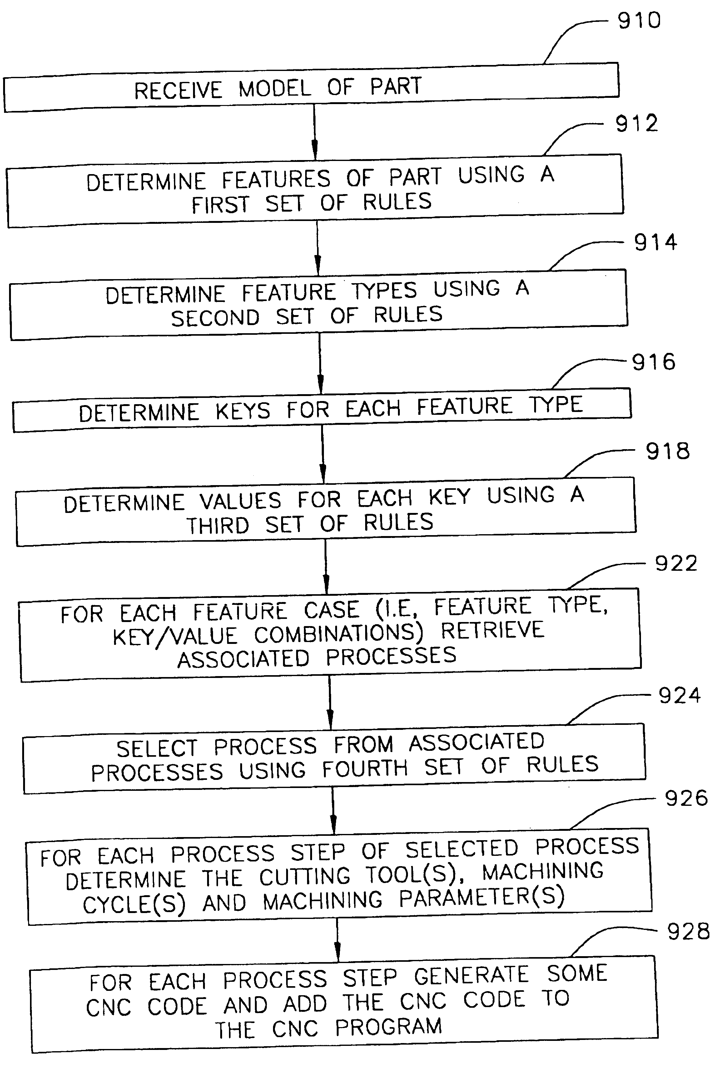
[0032]A part that is manufactured from one or more materials is composed of one or more features, for example, holes, pockets, slots. Each feature has one or more attributes which describe physical characteristics of a feature. For example, for a hole the attributes include the location, diameter, and depth of the hole. In the case of machining a part from a block of material using a CNC machine, each feature is cut out of the block of material. For each feature, there is a corresponding cutting process that includes selecting which cutting tools to use and the tool operations to be perfor...


PUM


Abstract

A system and method is disclosed for centralizing knowledge and improving programming for manufacturing a part. An embodiment includes a method for manufacturing the part. First, a model of the part is received. Next, a predetermined rule is retrieved from a computer readable medium having a plurality of predetermined rules. A feature of the geometric model is selected by evaluating the retrieved predetermined rule and a process is determined that is associated with the feature. Based on the process, computer code is generated to manufacture the part on a computer controlled machine.

Description

CROSS REFERENCES[0001]This application is with and incorporates by reference in its entirety U.S. Utility patent application Ser. No. 10 / 346,475 titled “Rule-based System and Method for Machining a Part” by Charles D. B. Mathews, et. al., filed Jan. 17, 2003.FIELD OF THE INVENTION[0002]The invention relates generally to the field of computer aided design and computer aided manufacturing (CAD / CAM) and in particular to manufacturing a part using one or more computer controlled machines.BACKGROUND OF THE INVENTION[0003]The use of a computer controlled machines to automatically machine parts has allowed the quick production of precise parts. For the specific case of machining parts, these machines are called computer numerically controlled (CNC) machines and are basically a computerized machinist that cuts material away from a block of material, e.g., metal or plastic, until the desired product is achieved. For example, a three-axis CNC milling machine has a cutting tool, an end mill, a...

Claims


Application Information

Patent Timeline
Patent Type & Authority Patents(United States)
IPC IPC(8): G06F19/00G05B19/4097G06F
CPCG05B19/4097G05B2219/31325G05B2219/35012G05B2219/36284G05B2219/35211G05B2219/35216G05B2219/35032Y02P90/02
Inventor MATTHEWS, CHARLES DUNCAN BARRINGTONGUSTAFSON, MICHAEL ALAN
Owner HEXAGON TECH CENT GMBH
Why Eureka
Try Eureka