Malfunction detecting system of engine cooling apparatus

a technology of engine cooling and detection system, which is applied in the direction of machines/engines, analogue processes for specific applications, instruments, etc., can solve the problems of inability to accurately ascertain the state of engine cooling, large difference between the coolant temperature and the intake air temperature, and large difference between the intake air temperature and the outside air temperature, etc., to achieve high accuracy

Active Publication Date: 2005-06-14
HONDA MOTOR CO LTD
View PDF3 Cites 14 Cited by
  • Summary
  • Abstract
  • Description
  • Claims
  • Application Information

AI Technical Summary

Benefits of technology

[0008]An object of the present invention is therefore to overcome this disadvantage by providing a malfunction detecting system of an engine cooling apparatus that by accurately detecting the state of engine cooling and discriminating malfunction based thereon can detect malfunction of an engine cooling apparatus, more specifically a radiator, still more specifically a thermostat with high accuracy.

Problems solved by technology

Immediately after shutdown, however, the difference between the coolant temperature and the intake air temperature is large, and the difference between the intake air temperature and the outside air temperature is also large.
When the outside air temperature is detected from the output of a sensor located in the engine compartment, however, the state of engine cooling cannot be accurately ascertained until the temperatures become equal.

Method used


Image

  • Malfunction detecting system of engine cooling apparatus
  • Malfunction detecting system of engine cooling apparatus
  • Malfunction detecting system of engine cooling apparatus

Examples


second embodiment

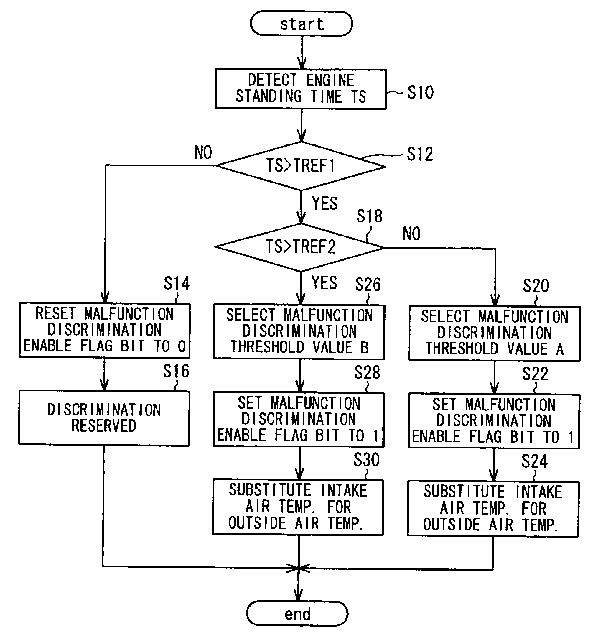
[0056]A malfunction detecting system of an engine cooling apparatus will now be explained with reference to the flow chart of FIG. 6, which is similar to the flow chart of FIG. 3. The illustrated program goes into operation when an ignition switch is turned on and is thereafter executed at regular intervals of, for example, 2 sec.

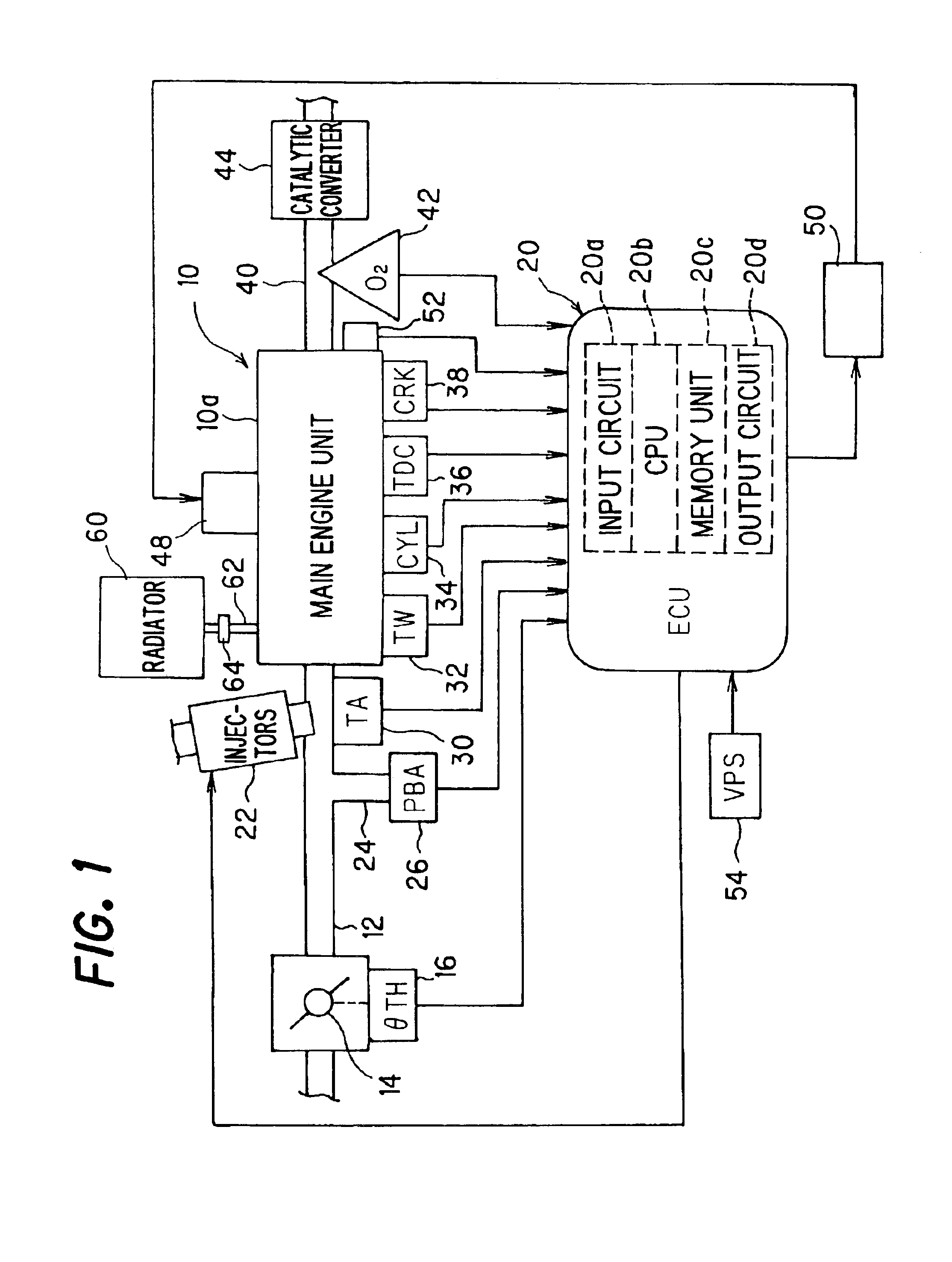
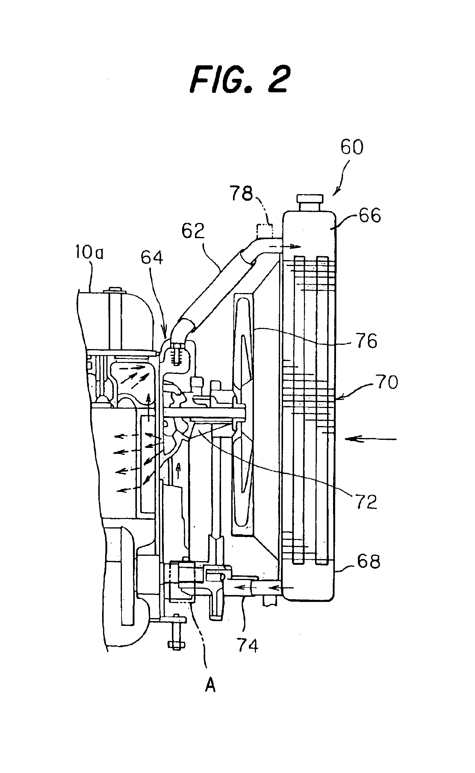
[0057]In this second embodiment, a temperature sensor 78 is installed at an appropriate location on the inlet pipe 62 downstream of the thermostat 64 as illustrated by a chain-dot line in FIG. 2 and outputs an electric (detection) signal representing the temperature of the coolant flowing through at least one of the inlet pipe 62 and outlet pipe 74 (more specifically, the inlet pipe 62 in the illustrated configuration) This temperature is referred to as the “radiator coolant temperature TR.” The output of the temperature sensor 78 is sent to the ECU 20.

first embodiment

[0058]Similarly to in the first embodiment, in S200, the period that the engine 10 was inoperative prior to starting (standing time period TS) is detected. Next, in S202, a check is made as to whether the detected standing time period TS exceeds the first predetermined time period TREF1. When the result is No, the bit of a malfunction discrimination enable flag is reset to 0 in S204 and discrimination or judgment regarding malfunction is reserved in S206.

[0059]When the result in S202 is Yes, a check is made in S208 as to whether the detected standing time period TS exceeds the second predetermined time period TREF2. When the result in S208 is No, a malfunction discrimination trigger temperature difference (malfunction discrimination execute threshold value) A (e.g., 40° C.) is selected in S210, the bit of the malfunction discrimination enable flag is set to 1 in S212 and the intake air temperature TA is substituted for or renamed as the outside air temperature in S214. When the resu...


PUM


Abstract

In a malfunction detecting system of an engine cooling apparatus constituted as a radiator having a thermostat that opens / closes a communicating passage between the engine and the radiator, estimated coolant temperature is calculated using a thermal load parameter correlated to rise in the coolant temperature after engine starting, whilst an engine standing time period is detected. Then, the detected engine standing time period is compared with a predetermined value and based on a result of comparison, one of preset threshold values including a malfunction discrimination threshold value and a malfunction discrimination execute threshold value is selected. The selected threshold value is then compared with the estimated coolant temperature or a difference between the estimated coolant temperature and the detected coolant temperature, and it is discriminated that the cooling apparatus has malfunctioned, when the estimated coolant temperature or the difference exceeds the malfunction discrimination threshold value. With this, the malfunction can be detected with high accuracy.

Description

BACKGROUND OF THE INVENTION[0001]1. Field of the Invention[0002]This invention relates to a malfunction detecting system of an engine cooling apparatus, more particularly to a malfunction detecting system of a radiator, still more particularly to a malfunction detecting system of a radiator thermostat.[0003]2. Description of the Related Art[0004]The internal combustion engine of a vehicle is equipped with a radiator (cooling apparatus) for cooling a coolant. The radiator is connected midway of a coolant communicating passage composed of an inlet pipe and an outlet pipe. A thermostat (shut-off valve) is installed in the communicating passage. The thermostat closes the communicating passage when the coolant temperature is low, such as just after engine starting, and opens it as the coolant temperature rises so that the coolant can enter the radiator to be cooled.[0005]Since the radiator is one of the on-board components of a vehicle, it is preferably checked for malfunction. It was fo...

Claims


Application Information

Patent Timeline
Patent Type & Authority Patents(United States)
IPC IPC(8): F01P11/14F01P11/16F01P7/16
CPCF01P11/16F01P2023/00F01P2031/00F01P2025/13F01P2025/52F01P2025/08
Inventor TSUKAMOTO, TOSHINORIGOSYO, EISAKU
Owner HONDA MOTOR CO LTD
Why Eureka
Try Eureka