Method and arrangement for determining a weight with a dynamic scale

a dynamic scale and weight technology, applied in the field of determining a weight with a dynamic scale, can solve the problems of increasing the length of the overall mail processing system, inability to control and control the motor, and the need for complicated control and control. the effect of known methods and devices

Inactive Publication Date: 2005-06-14
FRANCOTYP POSTALIA
View PDF13 Cites 13 Cited by
  • Summary
  • Abstract
  • Description
  • Claims
  • Application Information

AI Technical Summary

Benefits of technology

[0011]An object of the present invention is to provide a method for determining a weight with a dynamic scale and a dynamic scale operating according to the method wherein the aforementioned disadvantage of known methods and devices are avoided.

Problems solved by technology

Alternatively, the weighing length could in fact be increased and a reject compartment could be provided, however, this would increase the length of the overall mail processing system, which is not possible without significant refitting.
A complicated control and controllable motors are required for this purpose.
Given unequally distributed mass in the letter and high conveying speed, measuring errors occur.
Moreover, the letter can slide off the weighing pan due to its inertia given a stoppage.
The conveying time from the weighing location to the postage meter machine is selected short, however, the speed cannot be arbitrarily increased without increasing the risk of jamming.
The speed of the weighing is limited by the speed of the weight determination.
A disadvantage of this procedure is that one must wait at least half the period of a possibly-occurring harmonically decaying vibration.
Since the curve form in practice, however, is not always ideal, the actual period duration can only be derived after several periods.
A high degree of measuring uncertainty exists given measuring curves that do not proceed ideally.
None of the aforementioned solutions have any possibility for adaptation to a mail processing system that operates with a high throughput of postal matter.

Method used


Image

  • Method and arrangement for determining a weight with a dynamic scale
  • Method and arrangement for determining a weight with a dynamic scale
  • Method and arrangement for determining a weight with a dynamic scale

Examples


Embodiment Construction

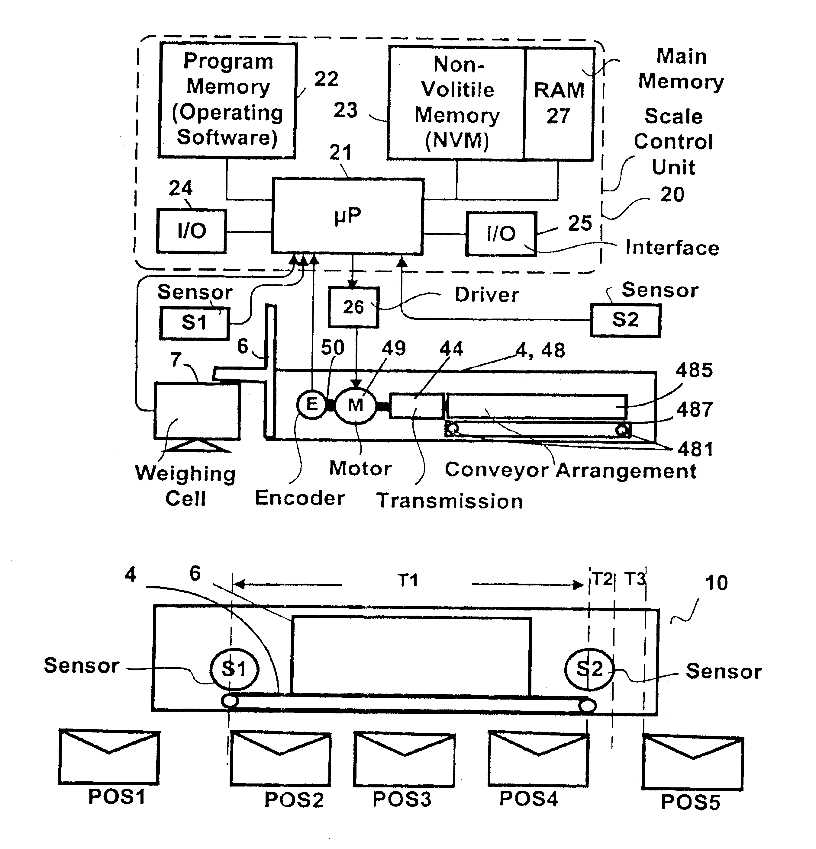
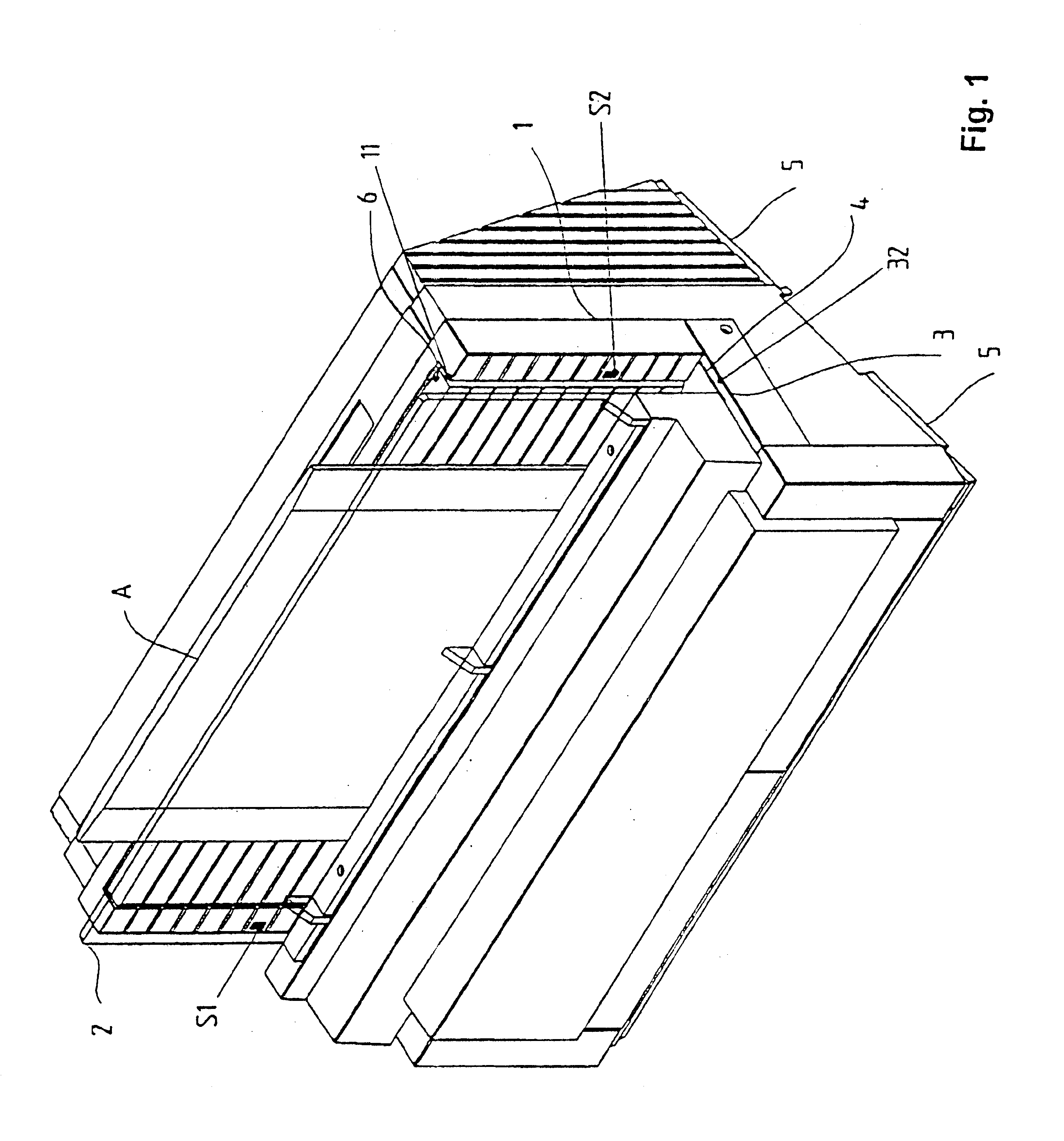
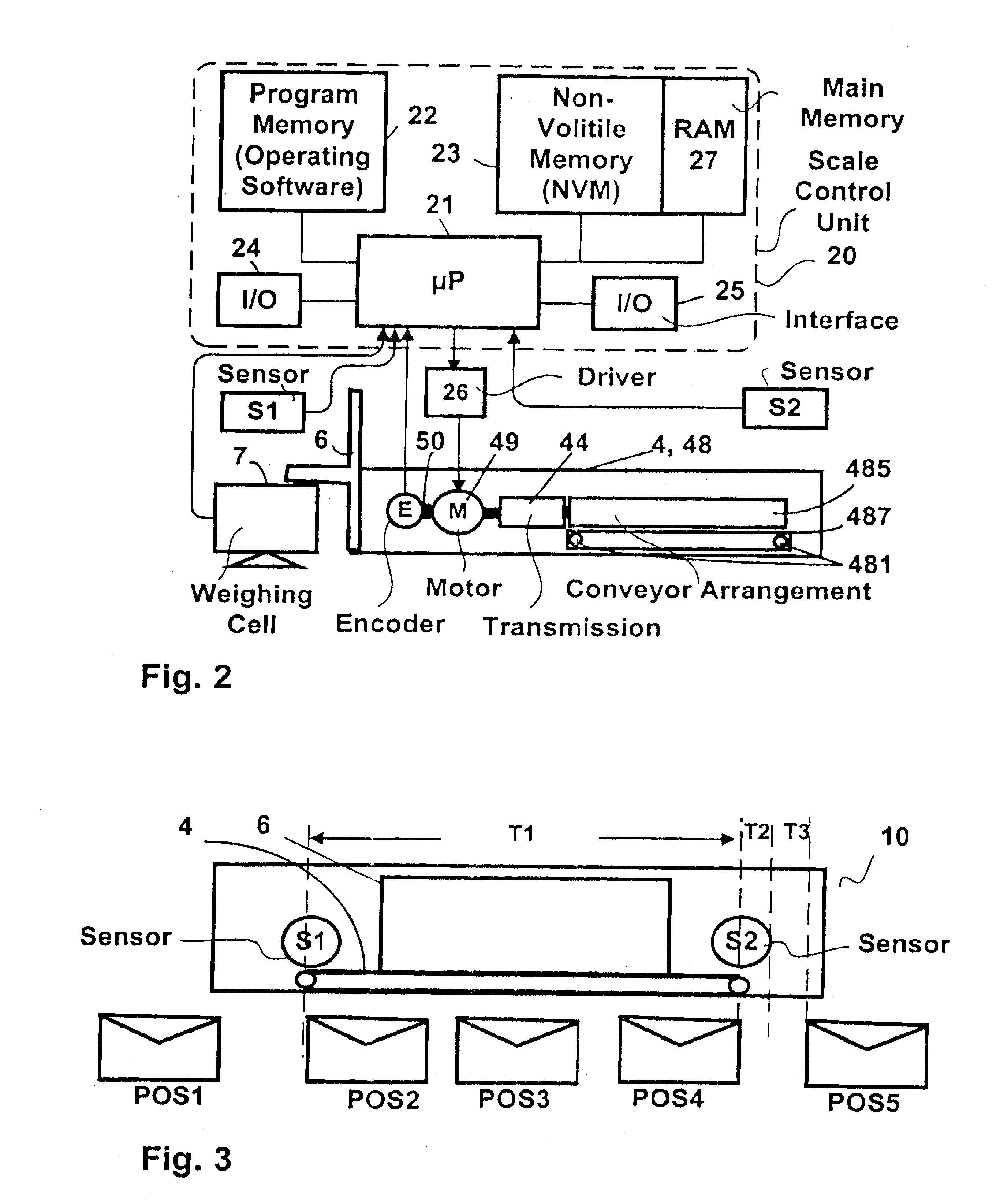
[0028]FIG. 1 shows a perspective view of a dynamic scale 10 that is fashioned for the transport of letters or other pieces of mail A standing on edge. The term “letter” will be used below as a generic representative of any type of item to be shipped or mailed. The letters A lie against a weighing pan 6 that is arranged in a recess 11 in a back guide wall 1 of the scale. Sensors S1 and S2 are arranged in the back guide wall 1 at both sides of the recess 11 for the weighing pan 6. A conveyor arrangement 4 having a conveyor belt that is moved under the sensors S1 and S2 lies at the level of the lower guide wall 3. The back guide wall 1 is inclined slightly toward the rear of the scale 10, preferably by 18° beyond the perpendicular. This corresponds to an optimization angle already determined for an automatic letter delivery and a postage meter machine (see German PS 196 05 014 and German PS 196 05 015. The lower guide wall 3 is arranged orthogonally relative to the back and also relati...


PUM


Abstract

A dynamic scale has a conveyor, a weighing pan, a weighing cell, sensors and an electronic control unit that, in addition to controlling the conveyor means (4), implements an evaluation of a number measured weight values that are obtained from the weighing cell and performs a measured value correction on the basis of specific parameters, and supplies a corrected weight value to a postage meter machine via an interface. A method for a control of the conveyor, evaluation of the measured values from the weighing cell, and formulation of a valid output weight value includes an overload check that is made by comparing a measured weight value lying in the middle of the number of measured values to at least one overload limit value, and formation of a decision parameter from the measured values, in a validity check, for comparison to at least one shutoff criterion. If the validity check determines that the measured values from the weighing cell are valid, they are used to form the output weight value.

Description

BACKGROUND OF THE INVENTION[0001]1. Field of the Invention[0002]The present invention is directed to a method for determining a weight with a dynamic scale according to an arrangement for the implementation of the method particularly for fast mixed mail processing in a franking system. The method is suitable for users of a mail processing system with a dynamic scale and a postage-calculating postage meter machine, or a system with a dynamic postage-calculating scale and a franking unit.[0003]2. Description of the Prior Art[0004]A digital scale is disclosed in German PS 37 35 036, wherein the analog output signal of a weighing cell is converted into a digital signal in an analog-to-digital converter. A microprocessor compares this digital signal to a zero value in order to derive the weight.[0005]U.S. Pat. No. 4,956,782 and British Specification 22 35 656 disclose semi-dynamic weighing. A user station arranged upstream in a mail flow can be a scale and a user station arranged downstr...

Claims


Application Information

Patent Timeline
Patent Type & Authority Patents(United States)
IPC IPC(8): G01G19/00
CPCG01G19/005
Inventor HUEBLER, UWE
Owner FRANCOTYP POSTALIA
Why Eureka
Try Eureka