Methods and systems for determining fatigue usage factors for reactor components

Inactive Publication Date: 2005-06-21
GENERAL ELECTRIC CO
View PDF0 Cites 7 Cited by
  • Summary
  • Abstract
  • Description
  • Claims
  • Application Information

AI Technical Summary

Problems solved by technology

Internal structures of operating BWRs are susceptible to various corrosive and cracking processes.
Feedwater nozzle cracking can be caused by thermal fatigue.
The thermal fatigue can be caused by a high cycling mechanism which involves rapid temperature cycling and usually initiates the cracking.
Also, a low cycle mechanism which is due to changes in the feedwater or reactor w

Method used


Image

  • Methods and systems for determining fatigue usage factors for reactor components
  • Methods and systems for determining fatigue usage factors for reactor components
  • Methods and systems for determining fatigue usage factors for reactor components

Examples


Embodiment Construction

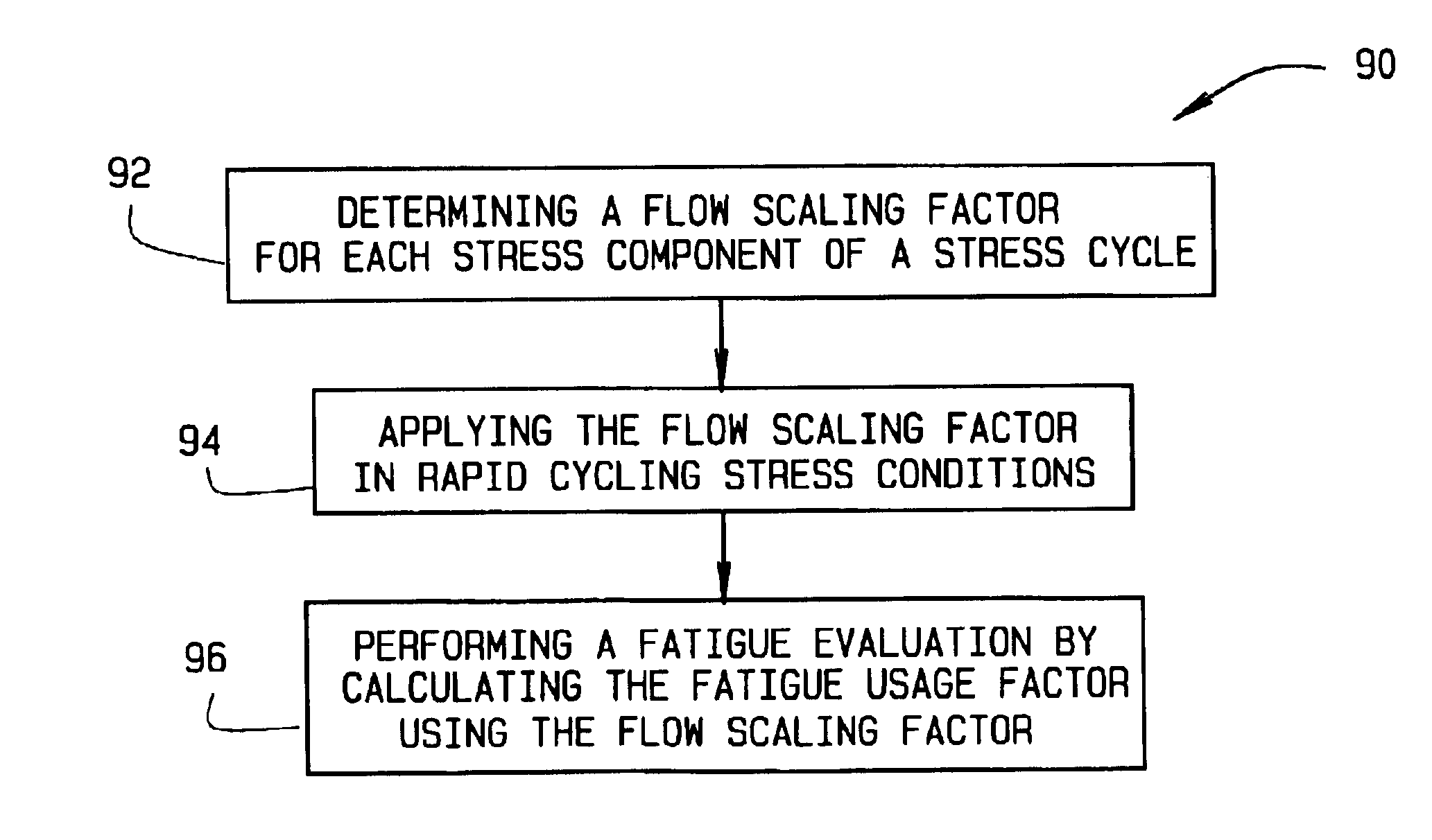
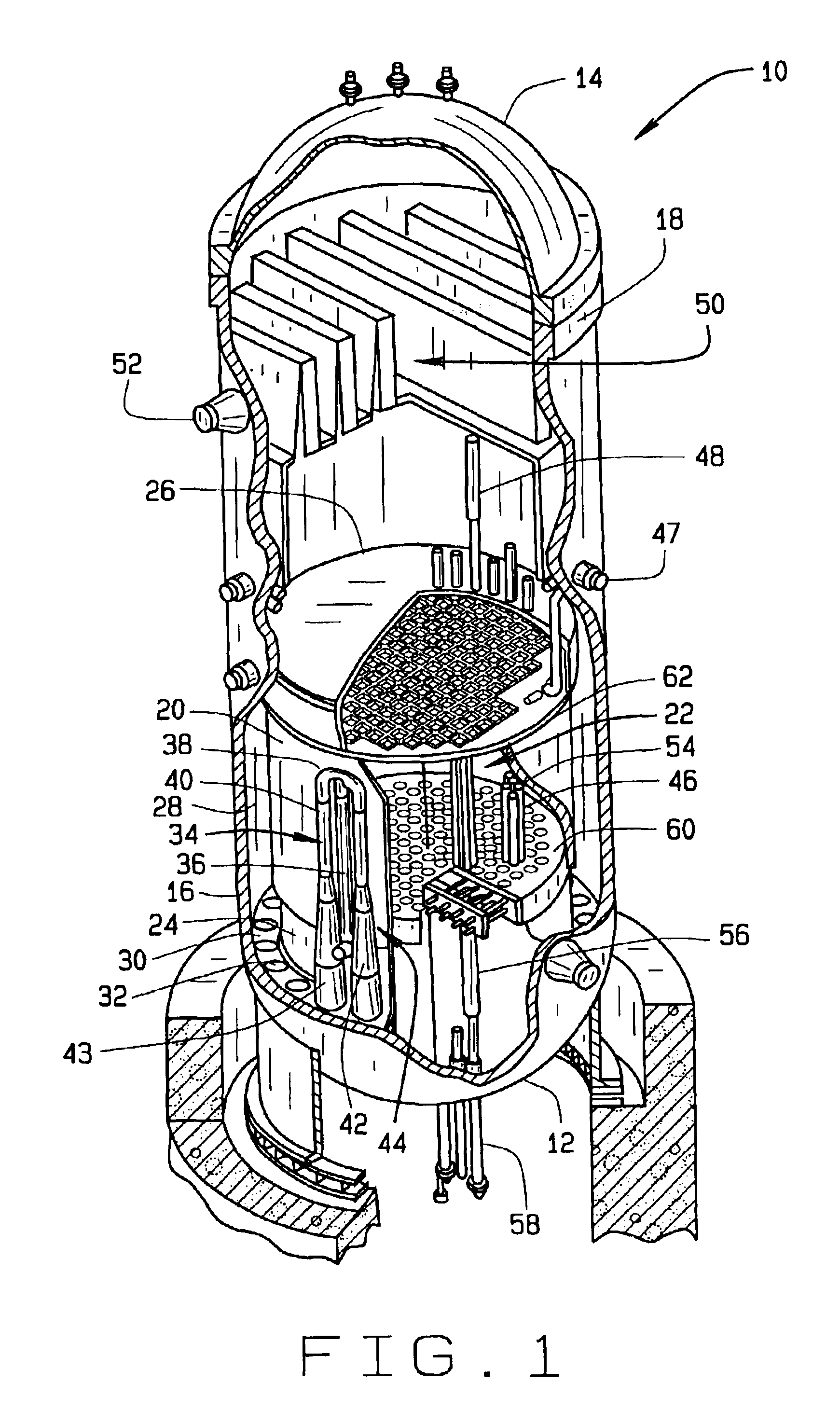
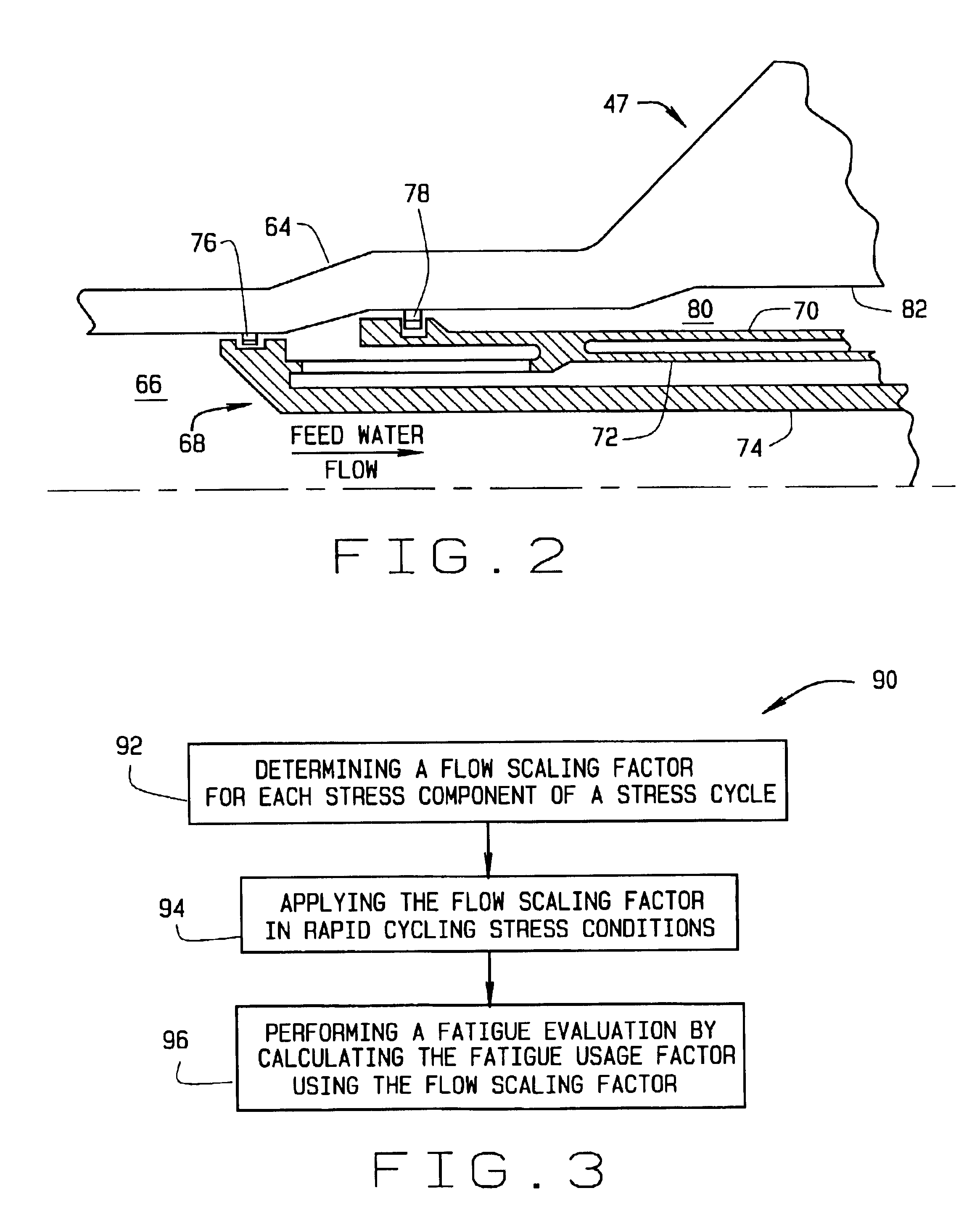
[0016]A method for determining a usage factor of a component in a reactor is described below in detail. Because of safety concerns, reactors have been licensed to operate at a maximum power that is less than what the reactor is capable of producing. From years of reactor operation it has been determined that the safety margins that have limited maximum reactor power output are larger than what are needed for safe reactor operation. As a result, reactors are being reconfigured to operate at higher maximum power. This extended power uprate (EPU) of reactors requires a new license from the governing nuclear regulatory agency. To obtain a license to operate a reactor at higher maximum power, a revised safety analysis report is required where the systems and components of the reactor are analyzed to determine if safe operation is obtainable at the extended power uprate. One of the components that is analyzed is the feedwater nozzles of the reactor. Particularly, an analysis is made of th...


PUM


Abstract

A method for calculating a fatigue usage factor of a component in a nuclear reactor includes determining a flow scaling factor for each stress component of a stress cycle, applying the flow scaling factor to rapid cycling stress conditions, and performing a fatique evaluation by calculating a fatigue usage factor using the flow scaling factor. The flow scaling factor is a ratio of a temperature fluctuation ratio at a first reactor operating condition divided by a temperature fluctuation ratio at a second reactor operating condition. The temperature fluctuation ratio is defined as a ratio of the metal temperature range over the fluid temperature range.

Description

BACKGROUND OF THE INVENTION[0001]This invention relates generally to nuclear reactors and more particularly, to a method for reducing the usage factor of the feedwater nozzle in a nuclear reactor.[0002]A reactor pressure vessel (RPV) of a boiling water reactor (BWR) typically has a generally cylindrical shape and is closed at both ends, e.g., by a bottom head and a removable top head. A core assembly is contained within the RPV and includes the core support plate, fuel bundles, control rod blades and a top guide. A core shroud typically surrounds the core assembly and is supported by a shroud support structure. Particularly, the shroud has a generally cylindrical shape and surrounds both the core plate and the top guide. There is a space or annulus located between the cylindrical reactor pressure vessel and the cylindrically shaped shroud.[0003]Internal structures of operating BWRs are susceptible to various corrosive and cracking processes. Stress corrosion cracking (SCC) is one kn...

Claims


Application Information

Patent Timeline
IPC IPC(8): G01N3/32G01N3/02G01N3/00
CPCG01N3/32G01N2203/0222G01N2203/0212
Inventor CHOE, HWANGBRANLUND, BETTY JANESRIDHAR, BETTADAPUR NARAYANARAO
Owner GENERAL ELECTRIC CO
Why Eureka
Try Eureka