Temperature-controlled injector for a chemical analysis unit

Active Publication Date: 2005-06-21
GERSTEL SYSTTECHN
View PDF22 Cites 36 Cited by
  • Summary
  • Abstract
  • Description
  • Claims
  • Application Information

AI Technical Summary

Benefits of technology

[0004]It is an object of the invention to provide a temperature-controlled injector which is of simplified structure a

Problems solved by technology

Apart from the fact that, in this design, there is a considerable outlay on assembly, the cycle times

Method used


Image

  • Temperature-controlled injector for a chemical analysis unit
  • Temperature-controlled injector for a chemical analysis unit
  • Temperature-controlled injector for a chemical analysis unit

Examples


Example

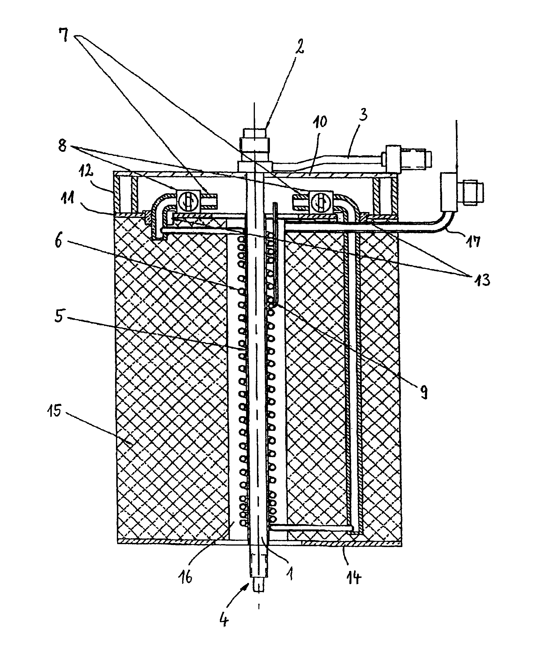
[0020]The injector which is illustrated in FIG. 1 comprises an injector tube 1 having an end piece 2 which is provided with a carrier-gas connection 3. At the end which is remote from the end piece 2, the injector tube 1 has a connection 4 for connection to a capillary column of a gas chromatograph.

[0021]The injector tube 1 is used, for example, in a cold injection device for a gas chromatograph to receive a sample injection tube which is provided with a liner in order to adsorb substances which are injected into the sample injection tube, for example using an injection needle, and are to be tested, in the cooled state, and then to release these substances into a carrier-gas stream, for example into a stream of nitrogen, by heating of the sample injection tube and to feed them to the capillary column with or without a split.

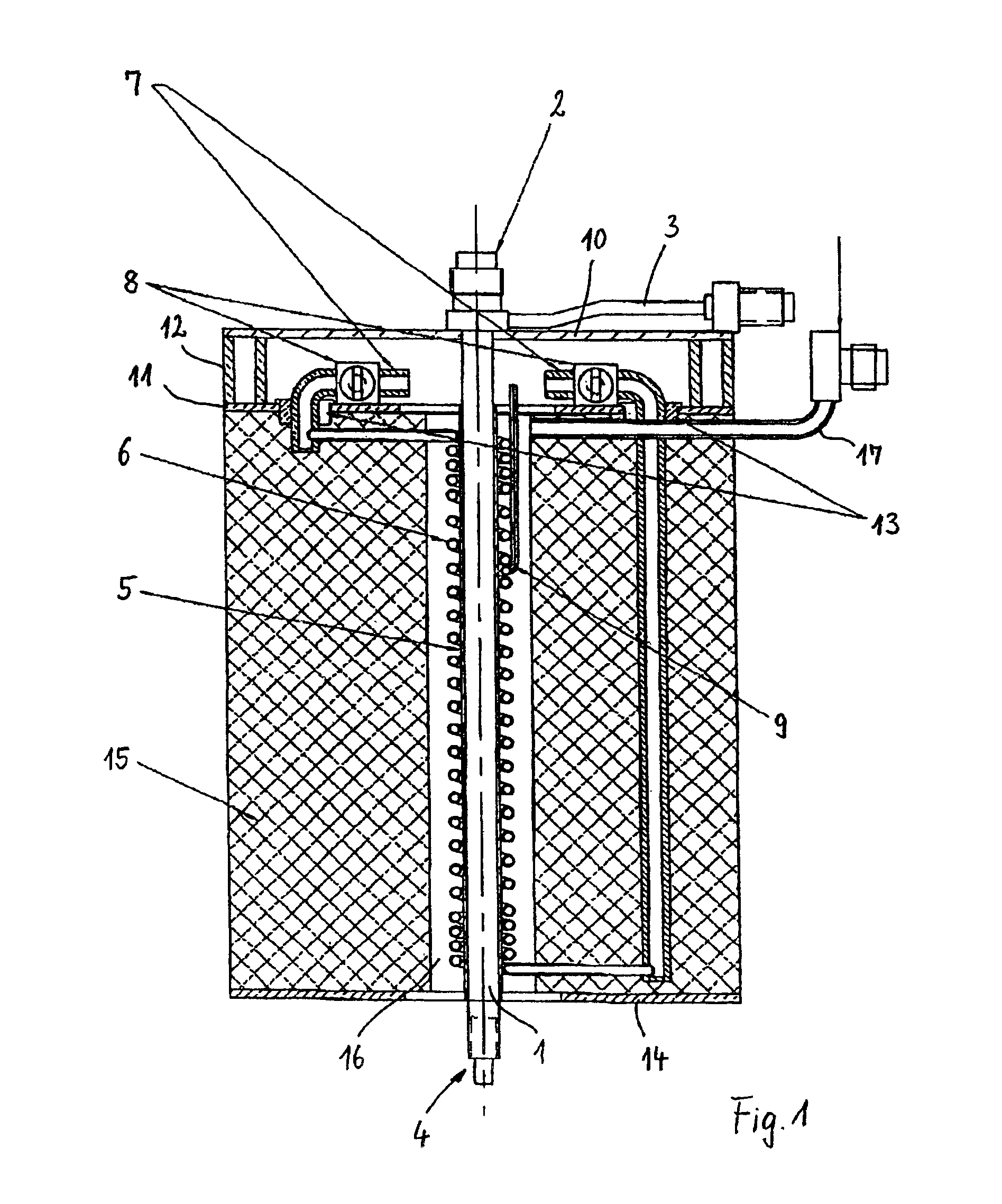
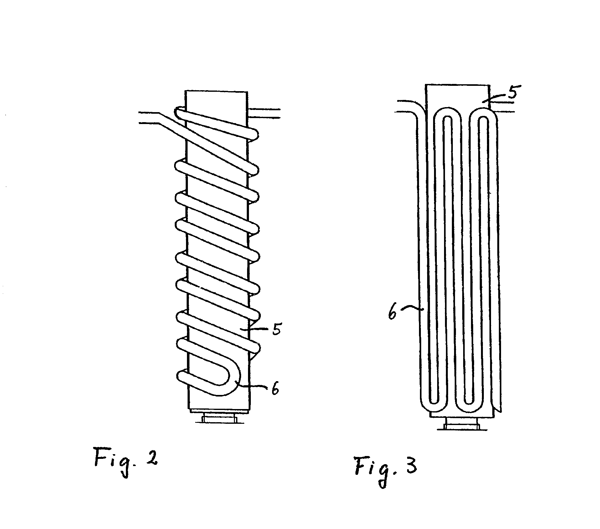
[0022]The injector tube 1 fits snugly inside a metallic receiving tube 5, which is provided on its outer side with an electrically insulating oxide layer. It is ...


PUM


Abstract

The invention relates to a temperature-controlled injector for a chemical analysis unit, in particular a gas chromatograph, comprising an injector tube, which can be received by a receiving tube, having a cooling system, which surrounds the receiving tube, through which coolant can flow, which has coolant connections and which is designed as a metallic tube coil, and a resistance heating system for the injector tube, in which injector the receiving tube consists of a material of good thermal conductivity, is electrically insulating towards the outside, and the tube coil rests on the receiving tube, has an electrical resistance which is sufficient to rapidly heat the injector tube and can be acted on by current via electrical connection pieces.

Description

FIELD OF THE INVENTION[0001]The invention relates to a temperature-controlled injector for a chemical analysis unit like a gas chromatograph. Such an injector is used to introduce samples to be analysed into a chemical analysis unit.BACKGROUND OF THE INVENTION[0002]From German Patent DE 198 10 109 C2 an injector for a chemical analysis unit, such as a gas chromatograph, which can be heated by means of a heater device in accordance with a predetermined temperature profile and can be cooled by means of a cooling device which concentrically surrounds the heater device, is known. The cooling device is in this case designed as a cooling hose which is arranged on a shell into which an injector tube can be fitted, with the heater device, for instance in the form of a heater cartridge, approximately as described in German Patent DE 198 17 017 C2. Apart from the fact that, in this design, there is a considerable outlay on assembly, the cycle times of the gas chromatograph are also correspond...

Claims


Application Information

Patent Timeline
IPC IPC(8): G01N30/00G01N30/12G01N30/30G01N30/16
CPCG01N30/12G01N2030/3061G01N2030/3046G01N2030/127
Inventor BREMER, RALFROSE, BERNHARD
Owner GERSTEL SYSTTECHN
Why Eureka
Try Eureka